| July 7th | |
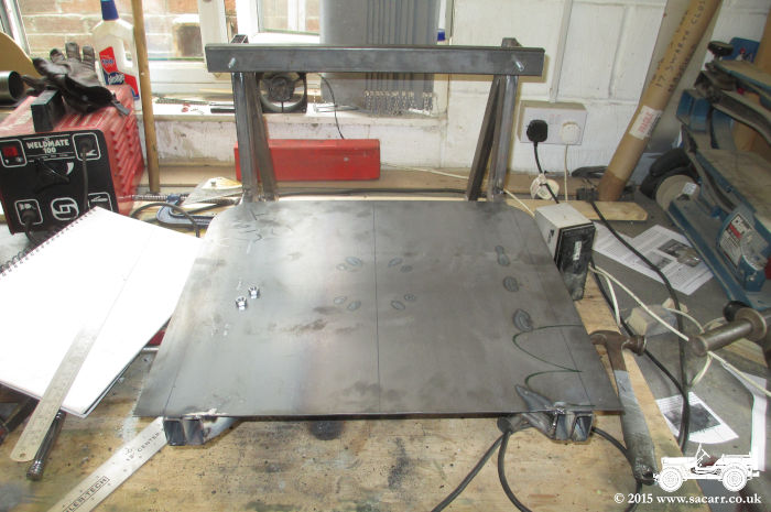
| I
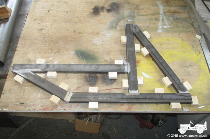
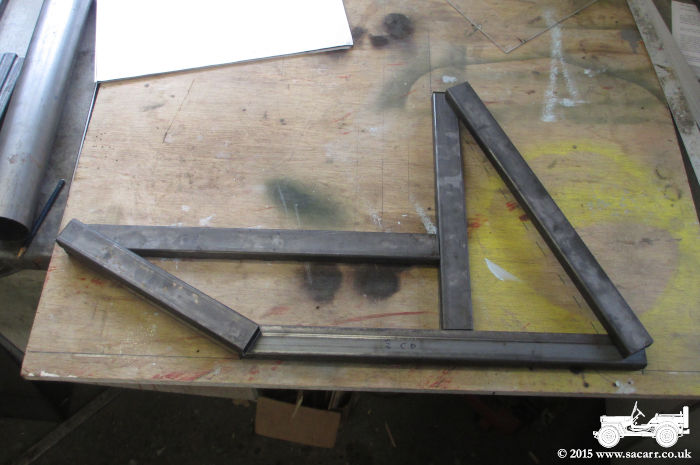
started with the metal frame seat support for when we're driving, now
referred to as the transit frames. This is made from some 40x20mm steel
box. The layout was drawn onto the building board and the pieces laid on
to check sizes and positions. Wooden blocks were then glued down to the
board to form a building jig, holding all the steel in the correct
positions. |
|
|
|
|
Once the blocks were dry, I started
marking out and cutting the box sections to fit together, cleaning the
surfaces were the welds were to be. To avoid twisting, I just tacked
each joint with a small weld, and then removed it from the jig. It was
turned over and another small tack placed on each joint. This now held
each joint from both sides, allowing the main weld to be made without
the heat pulling or twisting the sections. |
|
|
|
|
|
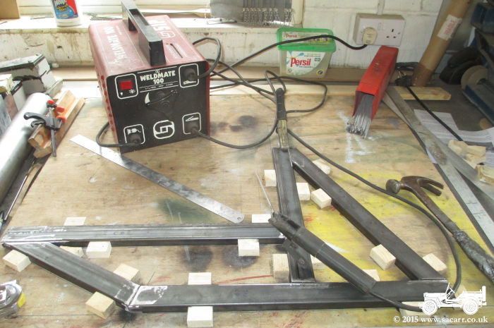
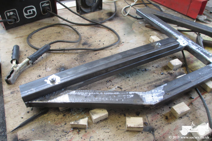
July 8th The following day, transit frame two
went into the jig and was welded up. Trying to conserve my
Oxy/Acetylene, I was using an arc welder. It was a fine balance between
having enough amps to get the arc going and too much power and burning
through the box section. |
|
|
|
|
|
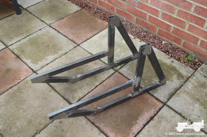
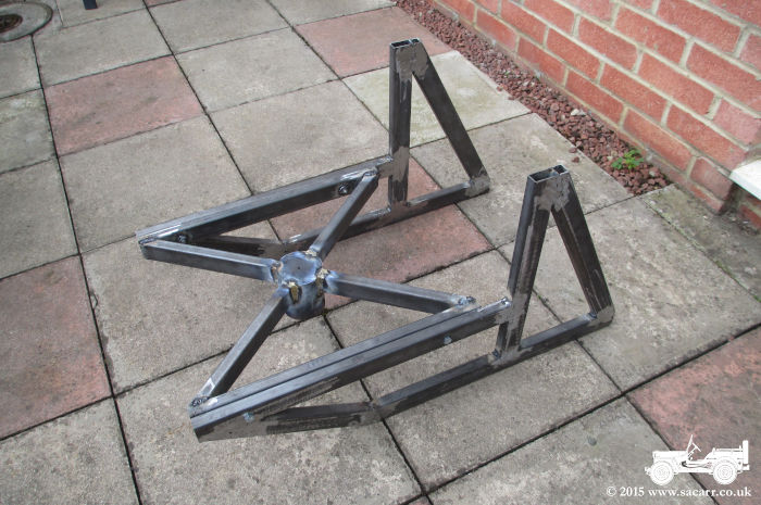
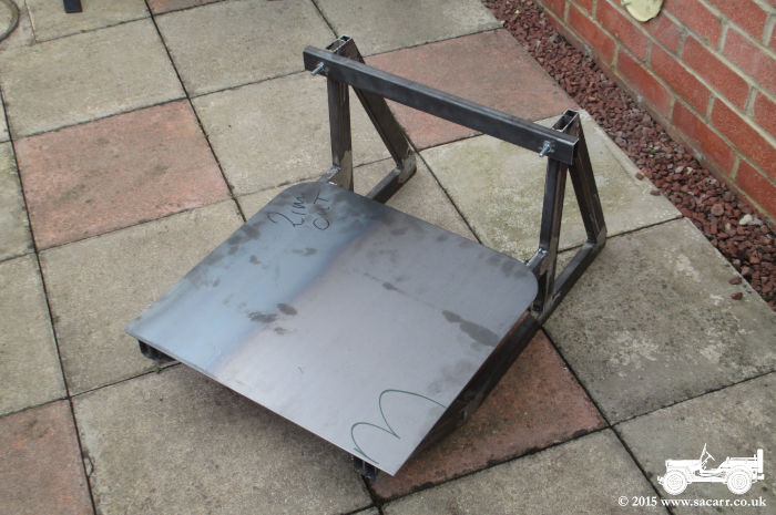
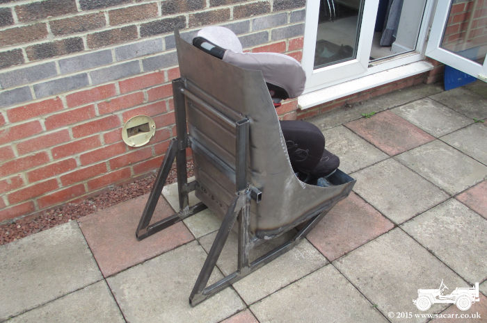
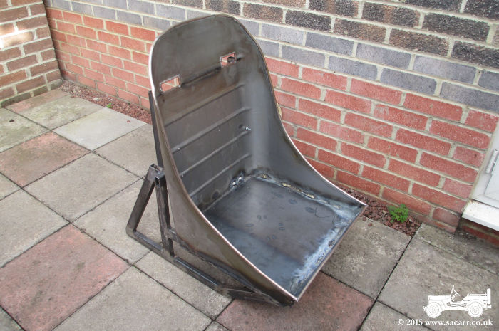
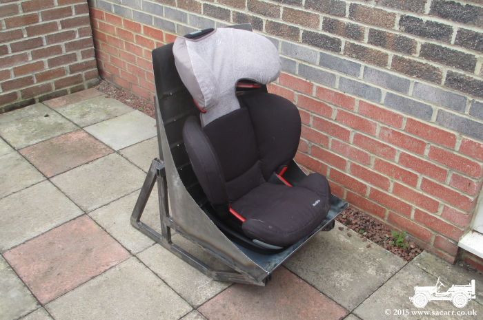
Once the two transit frames were made,
I began on the seat base support. This will brace the flat bottom of the
seat bucket and hold the pivot to allow the seat to rotate when being
used in the truck's observers position. This part of the frame would be
fastened to the seat, and would bolt to the transit frames when driving.
They would then be removed when the seat was used for display in the
observers position.
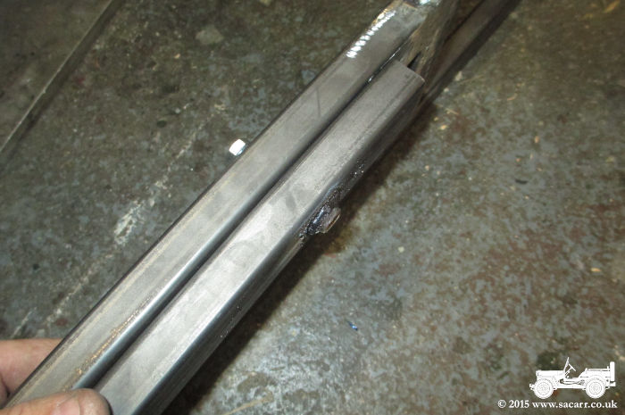
The two side frames of the seat base
were clamped to the transit frames, drilled and bolts fitted. The nuts
were then welded to these pieces. |
|
|
|
|
|
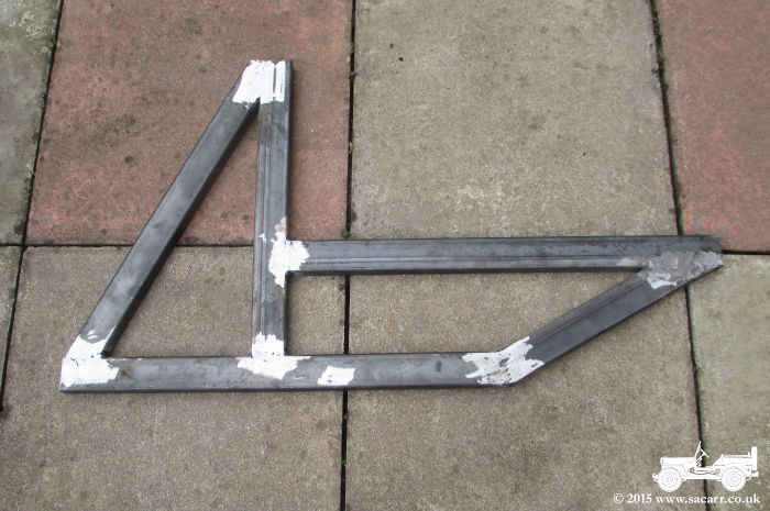
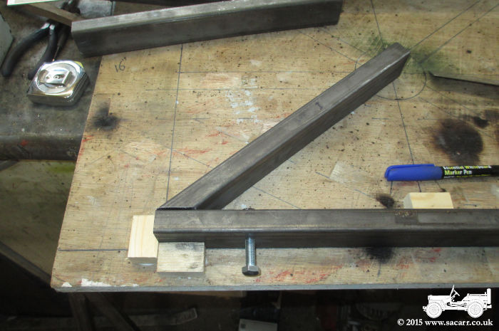
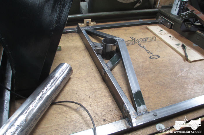
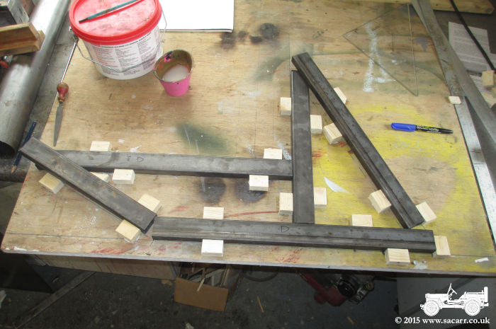
These two sections would then be welded
to diagonal braces which would join them to the centre pivot. The old
jig was chiseled off the board, it was sanded and the new seat base plan
drawn out on the wood. Once again, wooden blocks were used to jig the
box sections in the correct location. By school run time, I had the
first diagonal piece, cut to mate with the side rail. |
|
|
|
|
|
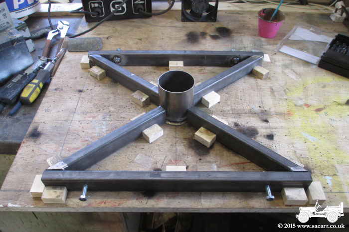
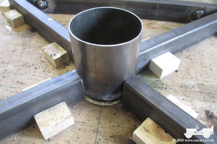
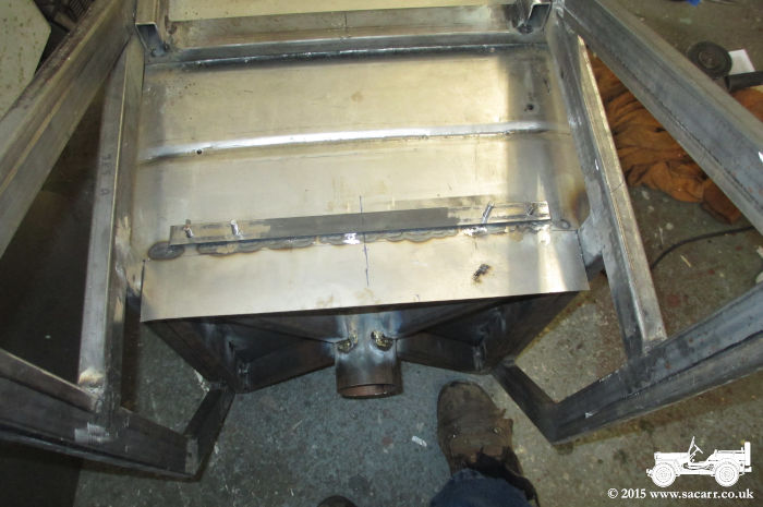
July 9th On Thursday 9th, work continued on
the seat base, finishing the jig and making the diagonal cuts on the
cross pieces. The tube had a 2mm sheet steel end brazed in, to act as an
additional bearing surface rather than the actual seat. The ends of the
cross pieces were then trimmed to length to fit this tube. |
|
|
|
|
|
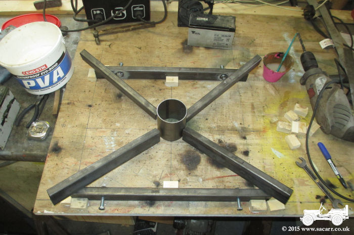
The cross pieces were tack welded to
the outer parts first, and a small tack weld added on the tube end,
being careful not to burn through it. It was then removed from the jig,
and the joints at the tube end were brazed; a safer option with the thin
walled centre tube. The outer end welds were then completed with the arc
welder. This allowed the three main pieces to be bolted together. |
|
|
|
|
|
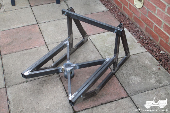
Two bolts were welded into the top of
the transit frames, onto which will attach the seat back. This back will
be braced by the cross member seen here. The last job of the day was to
cut the quarter round edges on the back of the 2mm seat base. On Monday
I hope to be starting the main bucket of the seat. |
|
|
|
|
|
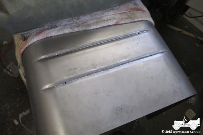
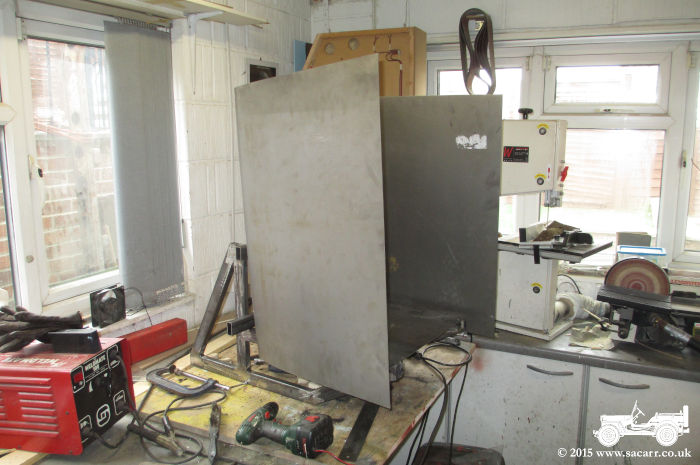
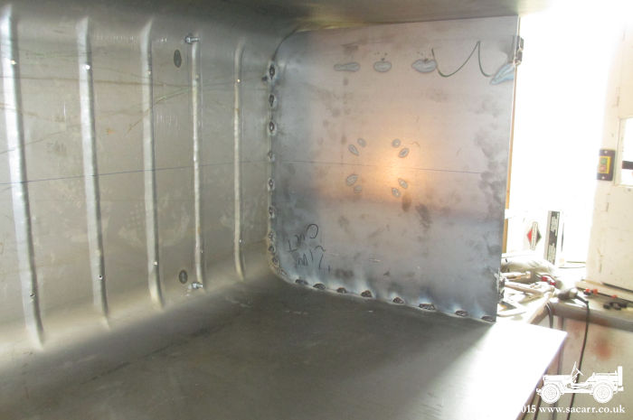
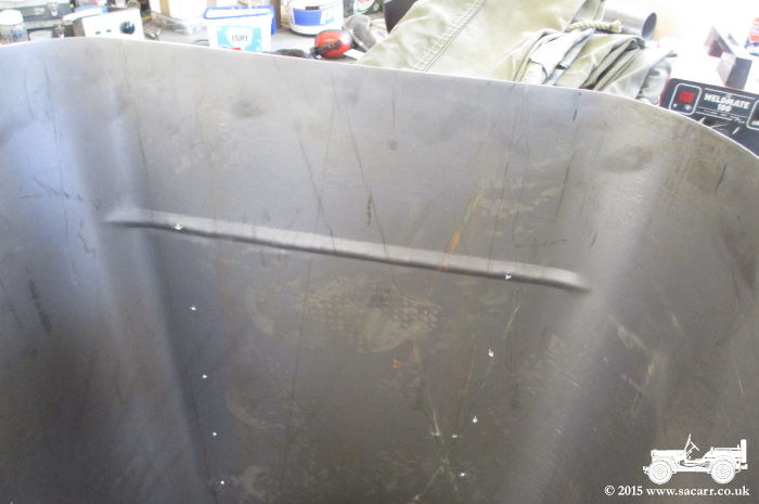
July 13th
On Monday 13th, I set off with a large sheet of steel to visit a friend with a sheet metal roller. I've not used a roller before, and while I'm sure I would have got to grips with it, it was easier to leave it to him. In return, I did some stencilling on some dummy bombs which took considerably longer than the metal rolling, but we both came away happy with the results of the day. The only thing that didn't get done was swaging the stiffeners in the seat back, as the swaging tool didn't have a deep enough throat. So that's the next job, making a male/female swaging tool to tap the stiffeners into the sheet metal.
|
|
|
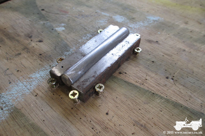
July 14th On the 14th, I decided to tackle the swaging. Metalworking has never been my favourite pastime, far too noisy, dirty and heavy! I much prefer wood, plastics and resin, but metal it had to be in this case, so I prepared myself for noise and mess. After having a think about a full length tool that would go right across the back of the seat, I decided against it due to the amount of force I would need to form along the whole piece in one go. Instead, I opted for a small tool around 4 inches long, that I could work my way across the metal with. A quick look in the scrap box found
some 10mm square steel and some round bar to make the male tool. These
were screwed down to a board to hold them in place for welding. Once the
ends were tacked, I turned the tool over and welded all the way along
the back of both joints, and then filled in the gap with additional
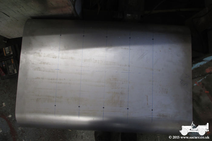
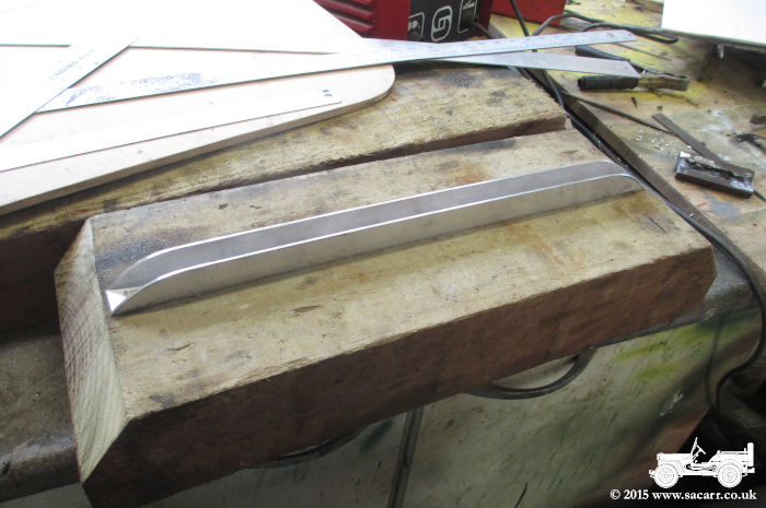
weld. The female tool was simply a piece
of aluminium channel, screwed to an offcut of railway sleeper. A piece
of 1.2mm steel sheet scrap was placed over the channel, the tool held
over the top, and with the swing of a large hammer, bang, the first part
of the swaging formed. I went back and forth until I got the result seen
in the picture below. I was very pleased with the result. The only
problem was the sheet moving around. Clamping a piece of steel the size
of the chair back was beyond the abilities of any of my clamps, but I
had an idea. |
|
|
|
|
After the test, I cut down the
aluminium channel and block of wood, so that they would fit inside the
back of the curved sheet metal. To hold the seat back still during the
swaging process, I opted for drilling small holes in the seat so that it
could be screwed through the female tool to hold the alignment
correctly. |
|
|
|
|
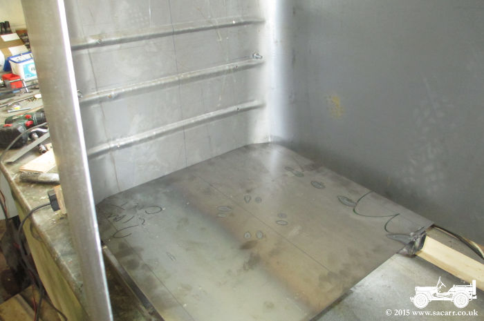
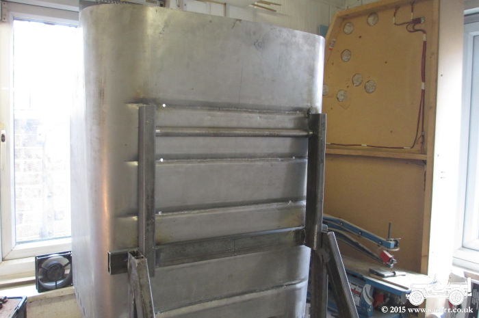
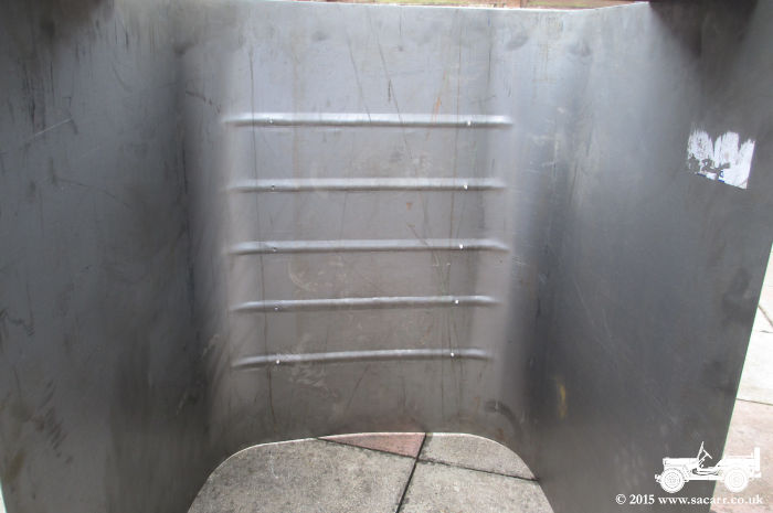
There weren't any more excuses not to get the big hammer out and make a start! The female tool/sleeper were placed on top of one stool and another piece of sleeper placed on a second stool to support the U shaped steel clear of the floor. To reduce the noise and ringing, I covered the area of steel not being worked on with an old towel, and then placed the folded up Dodge canvas on top of that. This worked pretty well to deaden the sound. The first swaging
area on the sheet was then lined up and screwed down to the female tool,
and battering began. To my surprise, it worked rather well, even around
the curve at the edge of the seat back. I didn't want to go too far in
this area in case it began to straighten the curve made yesterday. Once
the seat bucket is all welded up and cut to shape, the swaging around
the curved corners can be finished off. |
|
|
|
|
I was on a roll, and after the first
two were completed, the other three came soon after. They still need a
little tidying here and there with a small hammer, and I may yet fill in
the screw holes, but those things aren't urgent right now. Once the
swaging was complete, I welded the seat base to the centre post and
diagonal braces made last week. |
|
|
|
|
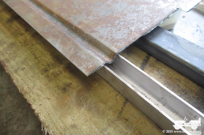
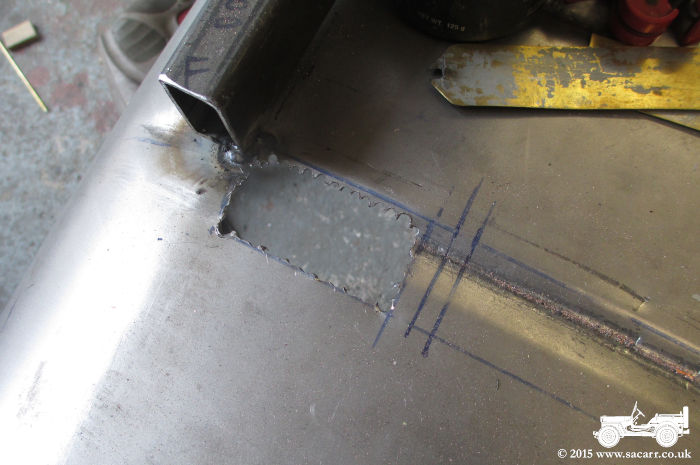
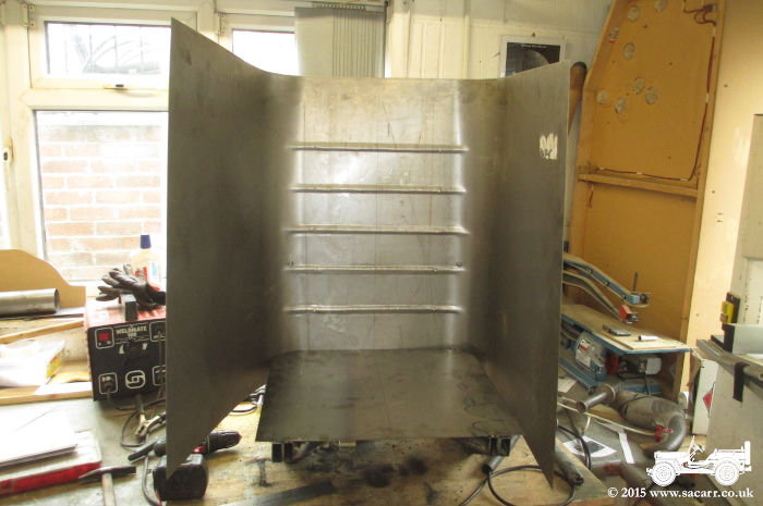
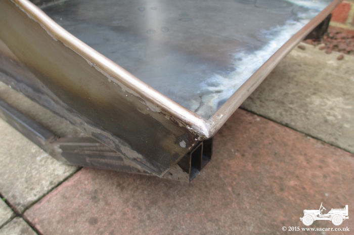
After the seat base was welded, I
didn't have long before school pick up time and childminding duties
started. The sheet was oversize, and to allow for the backwards rake,
the sheet needed slotting to clear the transit frames, allowing it to
drop lower than the seat base at the rear of the seat bucket. Two holes
were also drilled for the bolts on the transit frames that hold the
cross piece in place. |
|
|
|
|
Wooden wedges were hammered into the
rear of the frame to hold the seat back firmly against the seat base.
This will be the first part to be welded. Once the rear bottom seam is
welded, I can start to work around the corner and along the sides to the
front, but that's for another day, I had run out of time! |
|
|
|
|
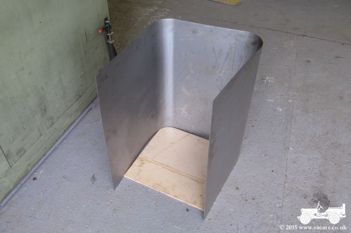
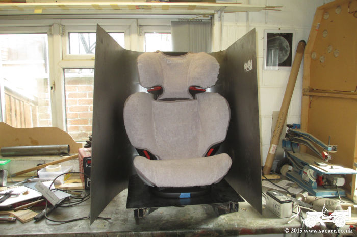
After a quick trial fit of the child
seat, I started welding the seat bucket sides. Because I didn't have any
really wide clamps, I made do with a few small ones. I also placed the
seat on its side with a number of old lead acid batteries on top, to
weight it down and close up the gap. |
|
|
|
|
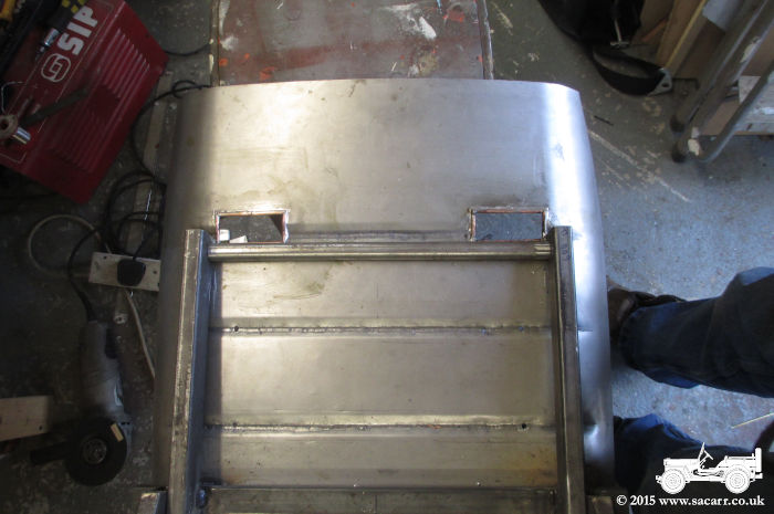
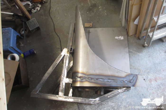
When both sides were welded to the
seat base, the front lip was welded in place. I also welded two uprights
to the cross piece and to the seat. At the top between these pieces,
I've wedged a tube which will be welded once I finalise its position. I
need to cut some holes in the seat back for the seat belts, and they
will wrap over this tube before heading down to be anchored to the
frame. |
|
|
|
|
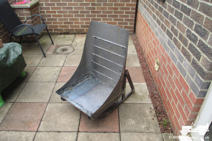
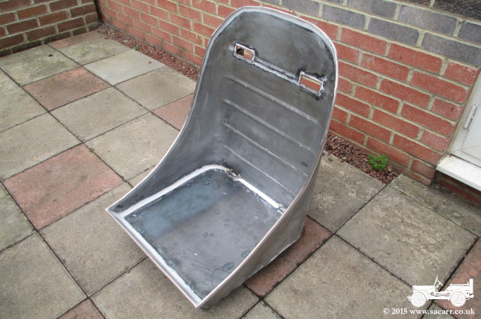
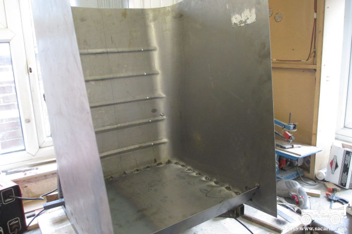
I marked out the side cut out next,
and roughly cut it with a 4.5 inch angle grinder. It was cut slightly
oversize to allow a little trimming room to smooth out the curve.
Measurements were taken from the first side and were then transferred to
side two which was then cut. The excess sheet extending down the sides
below the seat base were also trimmed, once again leaving them a little
over sized for now. The curving top to the seat back is yet to be cut,
but I'm very pleased with the way this is turning out. |
|
|
|
|
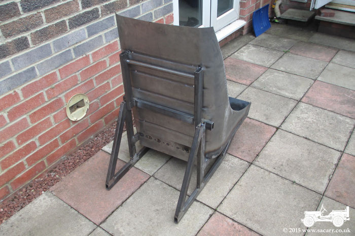
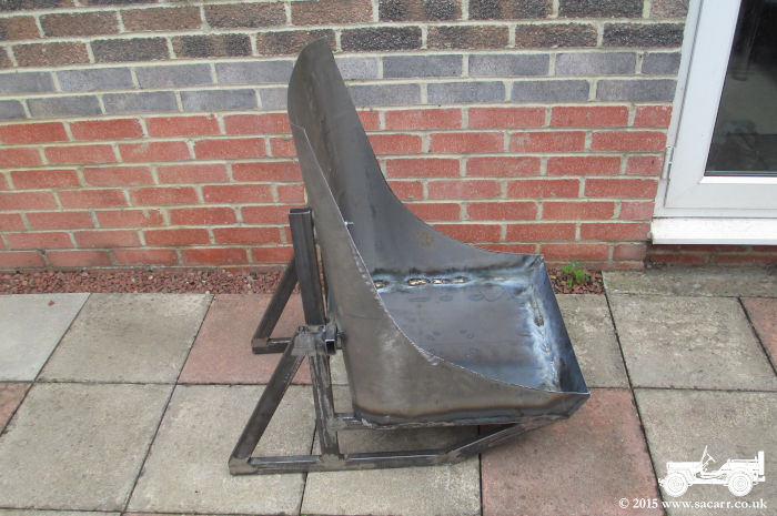
A couple more views from the side
and rear. |
|
|
|
|
After that, I did a quick trial fit
of the child seat again, and then it was time to pack up and do the
school run again! The next step will probably be the seatbelt slots and
Isofix seat fittings. |
|
|
|
|
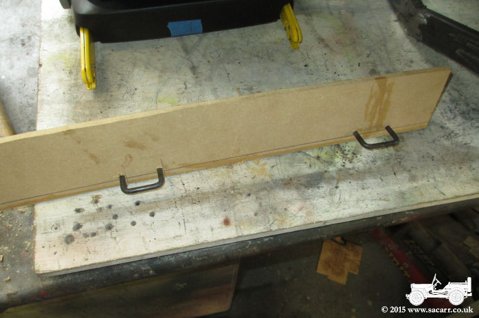
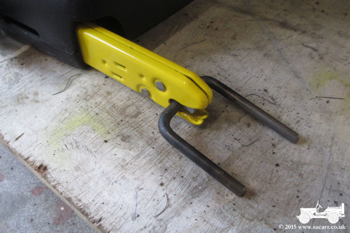
Time for the Isofix fittings next.
Some 6mm bar was heated and formed into two 'U' shapes that the isofix
fittings would attach to. The car seat was placed on a flat board to
work out the height of the fittings, and an MDF jig was made to test the
height of the loops. |
|
|
|
|
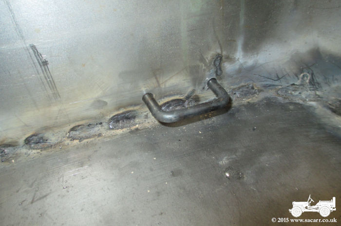
The MDF template was then used as a
drilling jig to position the hoops at the correct height in the base of
the seat bucket. A flat steel plate was welded on the reverse side of
the seat to spread the load of the fittings into the metal seat bucket. |
|
|
|
|
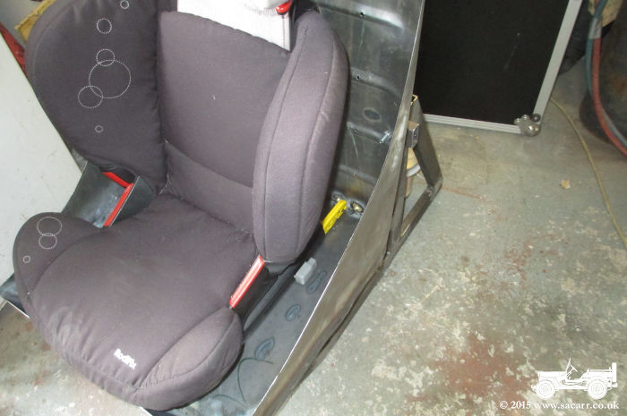
Yet another test fit showed the
yellow seat fittings were lining up perfectly with my Isofix
attachments. With that done, it was time to move on to the seat belts.
The shoulder straps go either side of the child seat head rest, placing
them right in line with the back of the seat. This meant that the seat
back had to be cut to allow the belts to pass through. After marking
out, I drilled a chain of holes until the centre part came out. The hole
was then cleaned up with a file. |
|
|
|
|
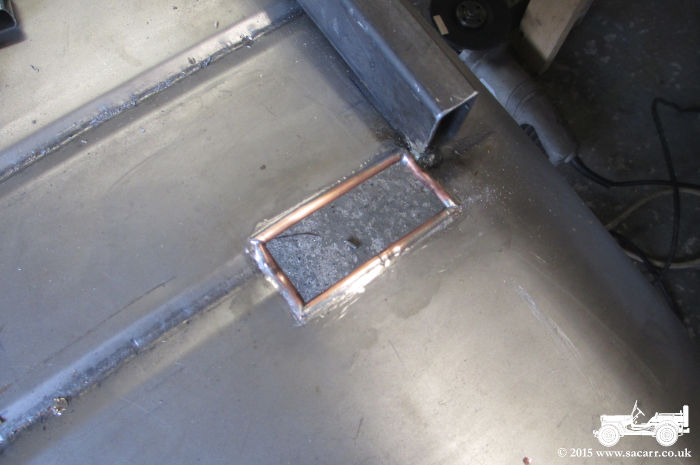
To stop the seat belt from fraying,
I edged the hole with copper brake pipe, slotted with a hacksaw so it
fitted over the sharp edge of the hole. The corners were bevelled so
they fitted together and the side pieces formed to match the swaging. It
was a fiddly job, but worked well. The second picture shows the two
lined holes from the rear. |
|
|
|
|
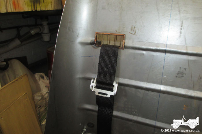
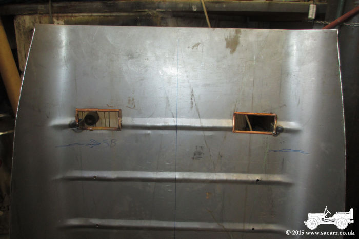
Here's the two lined holes from the
front, still needing soft soldering together. The holes had to be wide
enough to allow the adjusting buckle to pass through. |
|
|
|
|
After a morning of childminding, the little monster went out for a play date, so I was able to continue with the seat. The rough cut sides and back rest were measured and trimmed more accurately, using a template to match the curve on each side. Since I didn't have any rolling
equipment to edge the metal, I had an alternative method for putting a safe edge on the seat bucket - slitted copper pipe.
Now I thought it was going to be a hard job to slit the copper fuel pipe. I started with it in a vice and using a hacksaw, but I wasn't getting anywhere fast. |
|
|
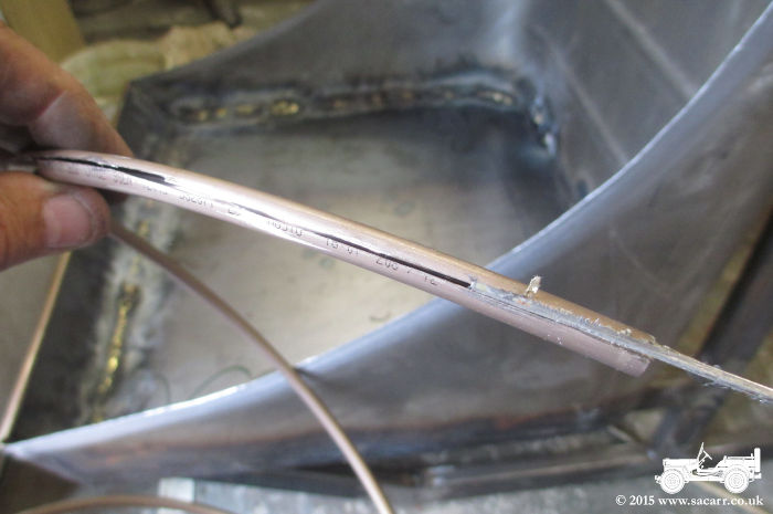
Then I had a brain wave of using my bandsaw. Not exactly the safest method, but you've got to live on the wild side every so often! So with the blade swapped to a 13tpi fine tooth one, I began slitting the tube on the outside of the coil.
|
|
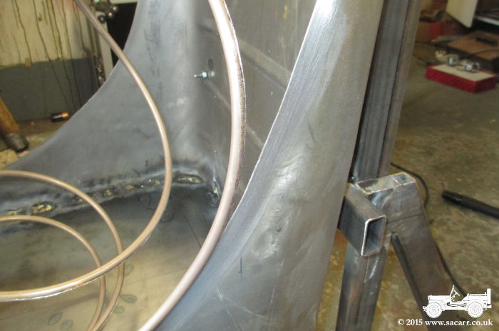
After the edge of the seat was cleaned up, the tube was pushed over, starting at the bottom. Because it was so springy, I was going to have to work around a bit at a time, soldering the tube before moving on to the next area. I just used soft solder to attach it, as it wasn't under any great load and I didn't want excess heat from brazing to distort the seat sides. |
|
|
|
|
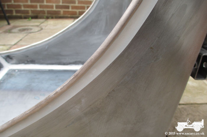
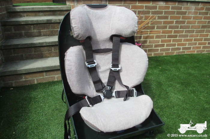
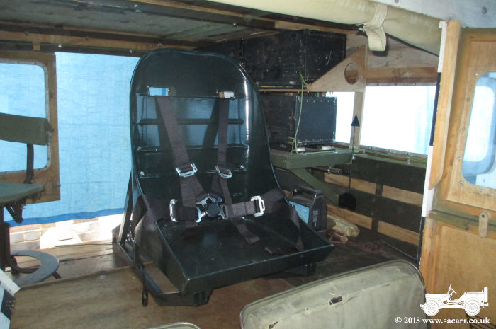
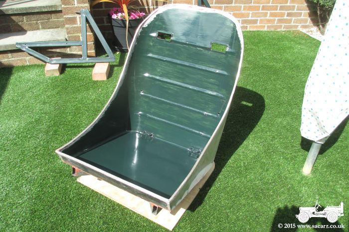
The edge is now nice and rounded and perfectly safe for little fingers. I'll probably give the soldered edge a thin skim of filler to tidy it up before painting. Other than some filler and paint, I think the observers seat is complete. I still need to work out where the four point harness will attach, and make the mounting in the floor of the Dodge which will support the seat while driving and also the pedestal when it is mounted in the observers position. |
|
|
|
|
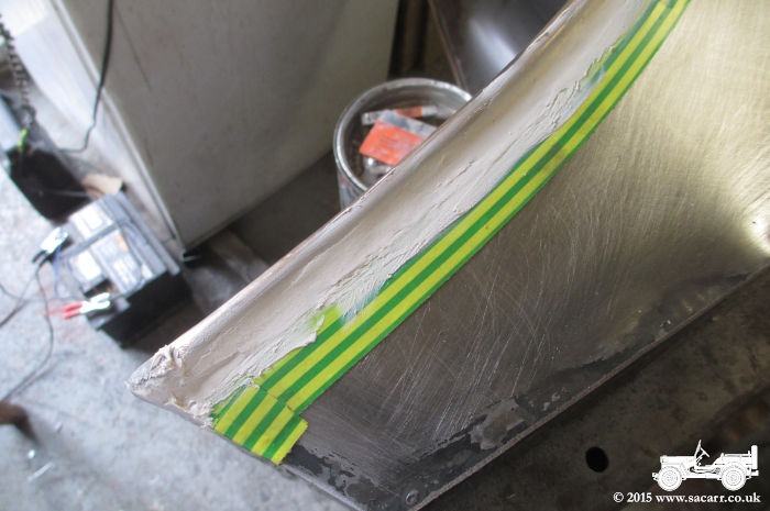
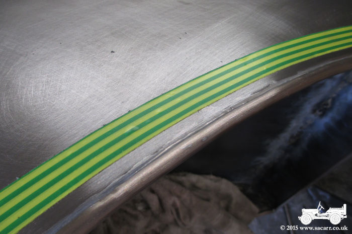
To simulate the wrapped edging on
the seat, I turned to a technique I've used in modelling to simulate
overlapping metal panels. Two layers of electricians tape were stuck
down where I wanted the panel edge to be, and then the area between the
tube and tape was filled with P38 body filler. |
|
|
|
|
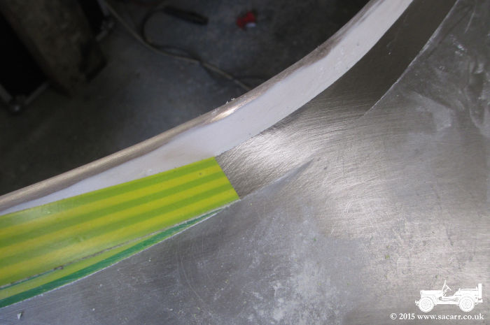
The filler was sanded flush with the
tape and then the tape was pulled away, leaving a nice edge. I may yet
simulate some rivets around this edge. |
|
|
|
|
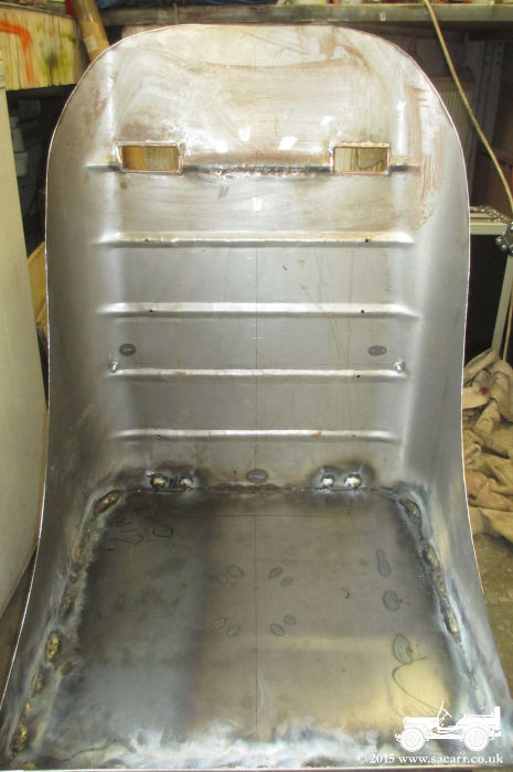
In addition to the tube edge, there was
quite a lot of other filling to do. All of the welds in the bottom of
the seat bucket were filleted, around the seat belt holes and around the
tube the belts wrap over. The edges of the flat reinforcing plate for
the isofixings was also filleted to tidy up its appearance.
The whole seat was also sanded down as it had a light coating of rust where the flux had been. The rest of the metal surfaces were also sanded to clean them off to bare metal ready for paint. It was a long day of filling, sanding and filling again. The inside surface doesn't need to be perfect, as it will be hidden with a yellow U.S. Air Corps seat cushion and back rest eventually, which will be fitted for display when the child seat comes out. |
|
|
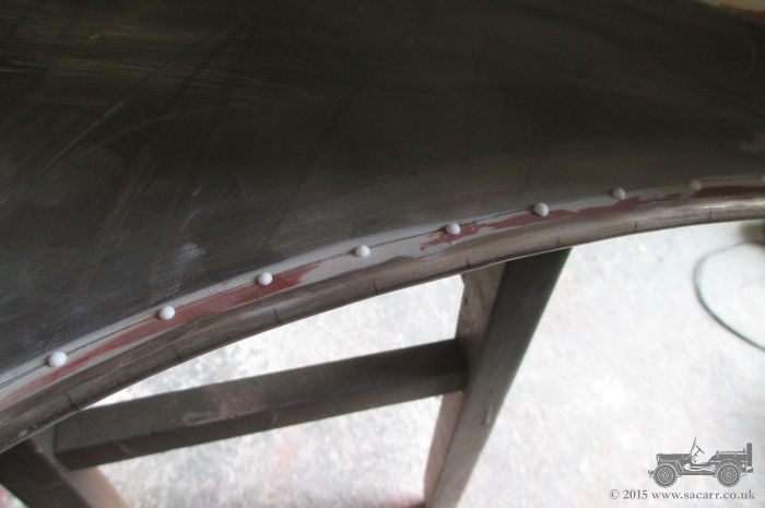
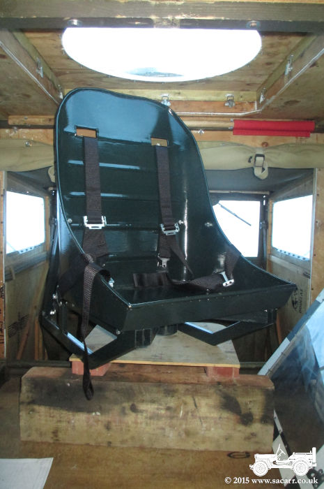
July 23rd
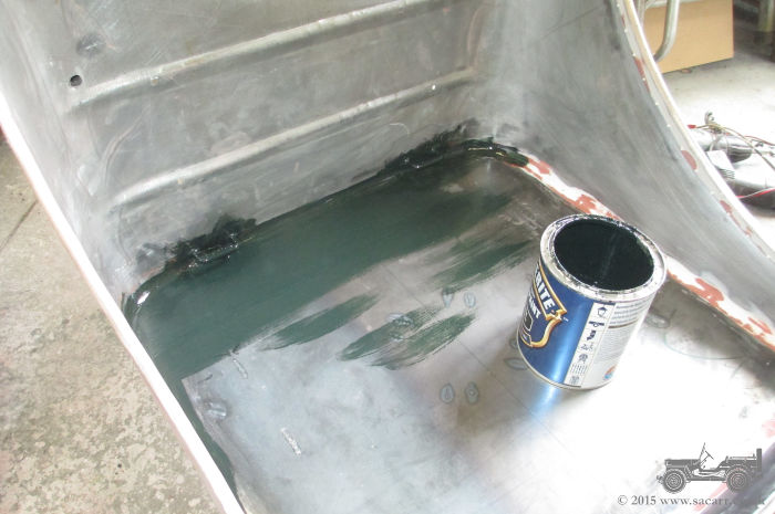
After further sanding and filling on the seat, it was time for some rivets around the edge. Fake rivets were added with blobs of waterproof PVA glue, applied with a syringe. The surface was force dried with a heat gun so that the rivet would hold its shape against gravity as the seat was turned to work on different areas. Hammerite Smooth Dark Green was a good match for Boeing cockpit Dull Dark Green. I had 1/3 of a tin left over from a previous project and used that first, but needed a second tin to be able to paint the seat and the framework that will be built into the floor of the Dodge. The side frames were given a coat of paint first and left out in the sun to bake. I then started on the inside of the seat bucket. The old paint was a bit thick, so was thinned for brushing, though the first coat was a bit streaky. |
|
|
|
|
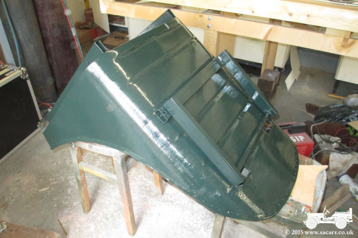
The
inside was painted up to, but not over the rivets, giving them more time for the glue to harden up. It baked outside for a little while before being brought back
inside and turned on its front. The bottom and back were then painted
before the first tin ran out and the seat was then left to dry
overnight. |
|
|
|
|
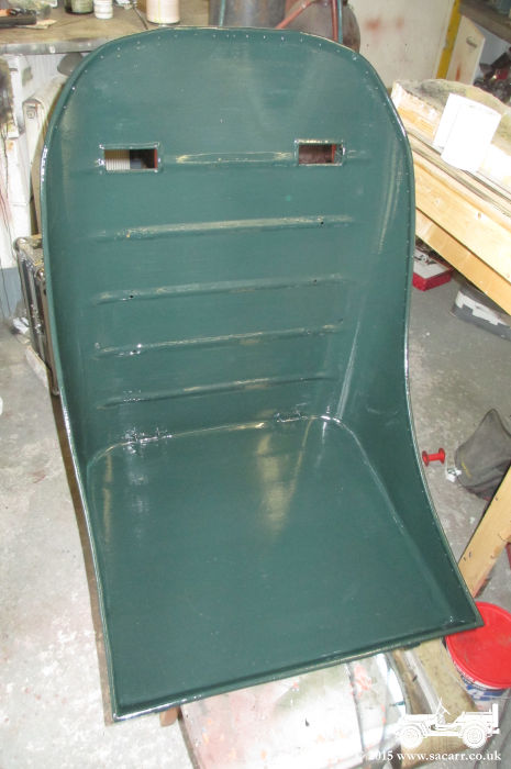
July 24th
I finished off the painting on the seat and transit frames today. Next job will be to bring the truck home and work out the framework for the Dodge floor that the seat will fasten to. 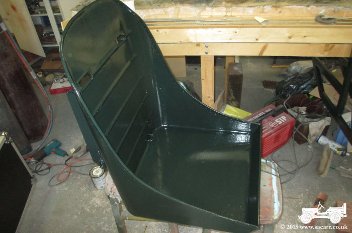
|
|
|
July 25th
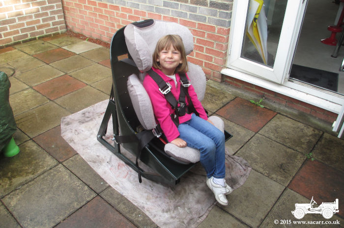
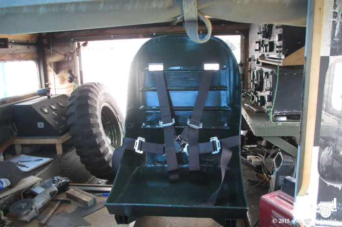
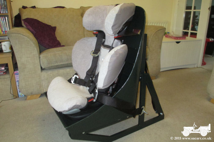
Seat harness fitting today. The four point harness fittings were clamped in place to work out the strap length and best fixing positions with the childseat in
place. Child wasn't available this afternoon while I was doing this, but there's plenty of adjustment in each of the four straps. |
|
|
|
|
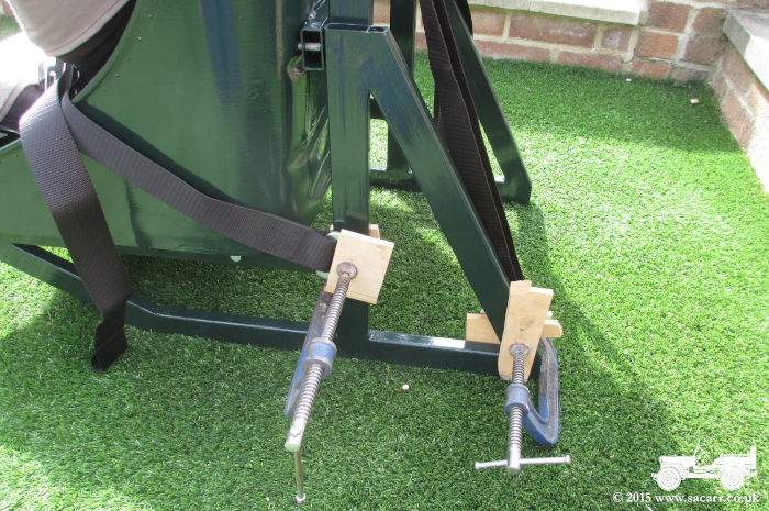
The shoulder straps are anchored on the rear inside of the frame while the waist is on the outside.
In the picture below, those just need the excess length of bolt trimming down.
To maintain pressure on the isofix fittings, I have two layers of wood with an 1/8 inch strip of rubber clamped between. Pushed in behind the seat, it keeps positive pressure on the fixings and stops the seat from swinging side to side. It could do with some matching paint.
|
|
|
The seat harness is all done! I just need the truck home for the floor mountings.
When the side transit frames are removed, so the seat can mount in the observers position, the belts go with them.
The last picture shows the boss giving her approval! |
|
|
|
|
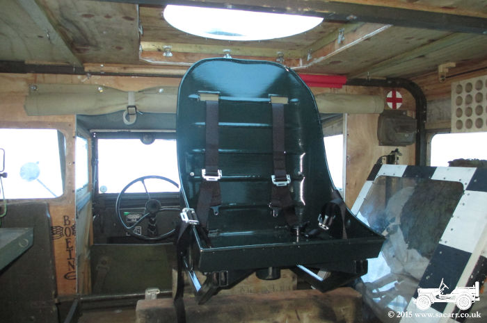
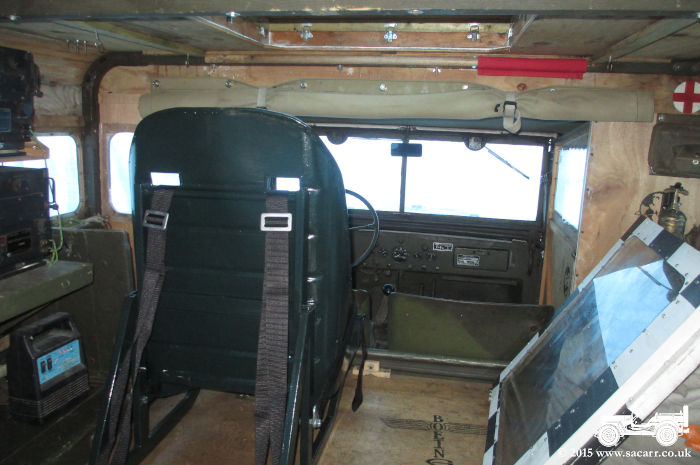
Despite heavy rain, the Dodge was
brought home from storage today, so I could start planning the seat
mounting structure. After getting the rain cover over the Dodge, I
lifted the seat into the back to work out the mounting location. As with
the last seat, it is positioned behind the driver which gives the least
restriction on my visibility when driving. |
|
|
|
|
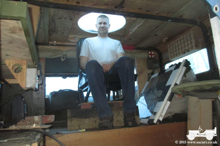
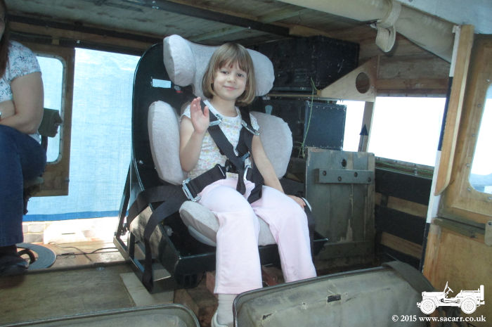
With the passenger installed in the
seat, there was plenty of leg room and still ample clearance to lift the
seat headrest as she grows. Once I'd made a few measurements and notes
on its position, I brought a few big chunks of wood from the workshop to
pack up the seat to the correct height under the observers dome.
Considering I hadn't had the truck at home though the whole of the
planning and construction, it was fitting reasonably well.However, I
didn't have much flexibility in the size of the metal seat, as this was
dictated by the child seat it had to contain. |
|
|
|
|
After a few changes of height, I
finalised the required position to put my head in the right place in the
dome. At present, the rotation of the chair is limited by the back rest
touching the edge of the dome cut out. This is enough movement for now,
but should I want more rotation, I can enlarge the raised area that the
dome sits on.
|
|
|
July 28th
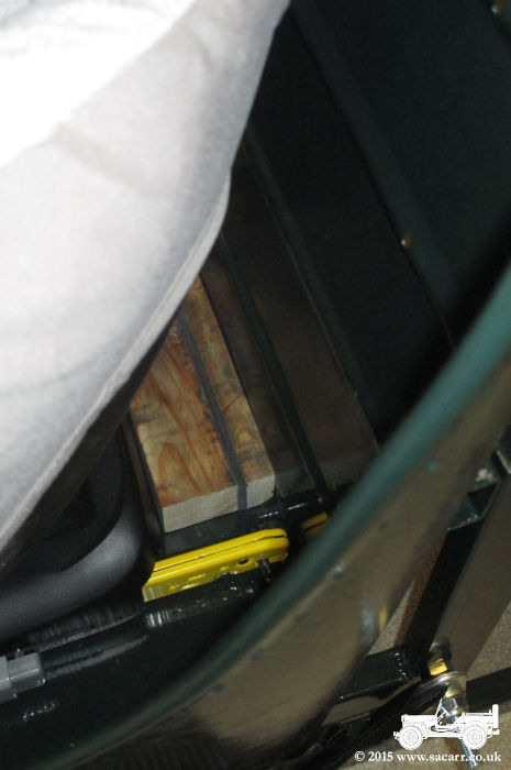
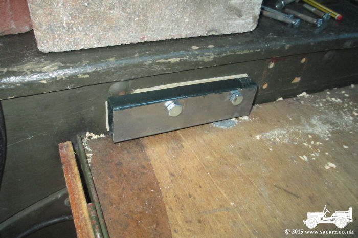
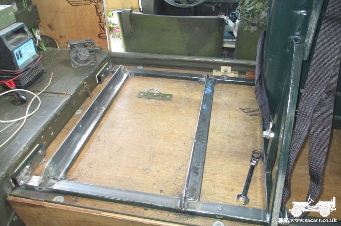
The morning was spent out shopping for the additional steel work required. To speed up the order, I got the metal in several long lengths to cut myself, rather than waiting overnight to have all the parts cut for me. The four empty bolt holes in the first picture show where the old child seat fittings were attached. The bolts had been in for five years, and with the nuts and threads exposed to the weather in the wheel arch, were quite tight to remove. Four steel box sections were bolted through the sides of the truck. The hidden faces were painted before hand, which held things up while they dried. 1/8 inch ply packing pieces were fitted behind each box section to make removal easier should it be needed. The bolts can be removed, the ply packers knocked out, which will then give 1/4 inch of free play between the frame and the sides of the body.
The two cross members are cut to length and painted on their undersides, but were not yet welded
in for this picture. The following day was child care all day, so no further progress until the 30th. The cross pieces would later have an additional bolt in the centre through the
floor. |
|
|
|
|
|
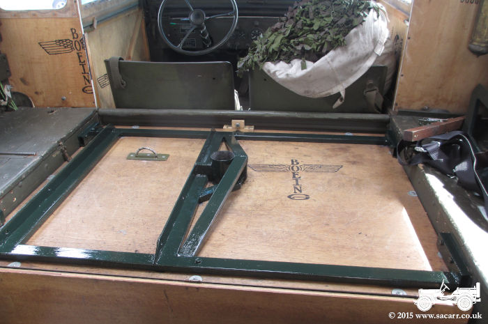
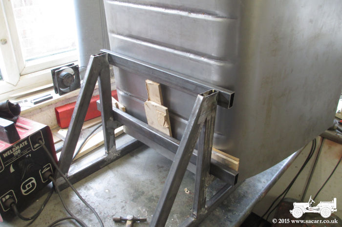
July 30th |
|
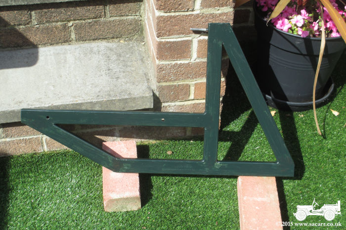
|
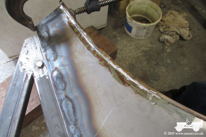
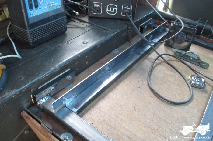
The cross pieces are welded and the seat supports are part built. They are made from box section with a flat plate welded to the side, forming an 'L' section. They
also need the underside painted before fitting.
|
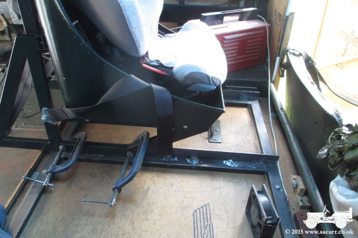
First, the seat fixing bolts needed drilling. The seat was clamped to the supports in the correct position for ample leg room. The supports lift the seat clear of the hinged door for the under floor spare wheel and tool storage.
|
|
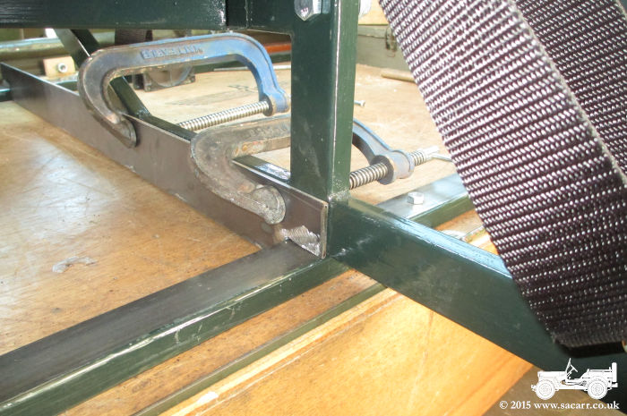
With
both sides clamped to the support rails, the chair and its rails were
lifted out of the truck onto the lawn for drilling the fixing holes. The bolts aren't fully threaded so the load bearing areas aren't weakened by the threads.
However, the nuts were bottoming out before clamping up the seat, so a 3mm washer was welded to the flat plate to give the required thickness ( not seen from this side ). |
|
|
|
|
|
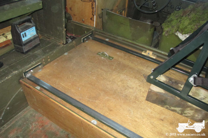
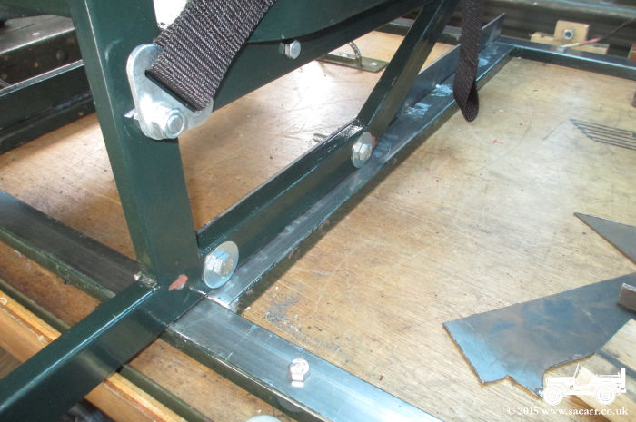
The seat was now bolted to its rails, but they were free to slide side to side so I could work out the best position to give clearance for the removal of the bolts that hold the frame into the truck.
|
The supports are now painted and welded down, and the flat plate uprights have had their ends rounded off. The centre bolt in the front and rear cross members can be seen in this shot.
|
|
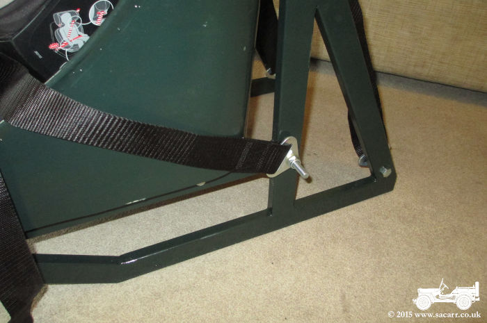
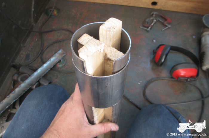
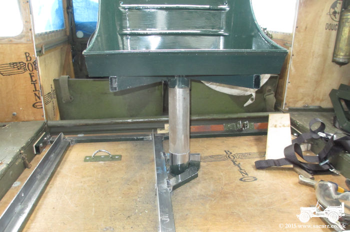
In between the seat mounting frame, I was working on the pedestal for the seat in the observers position. The tube in the base of the seat and the one that will be on the floor are 3 inches diameter. However, unlike model making brass metalwork sections, steel doesn't come in nice concentric sizes.
I tried reducing a 3 inch tube to fit by taking slices out and welding it back together, but than ended up far away from being circular! |
|
|
The only smaller size I could find was 2.5 inches, a full 1/2 inch smaller. Making one slice down the welded tube allowed it to spring open 1/4 inch. I figured if I could stretch it and weld a piece of the failed tube in, it should work ( I hoped! ).
Wooden supports inside the tube, forced the diameter larger until it was a pretty good fit in the 3 inch tube which would be fixed to the floor.
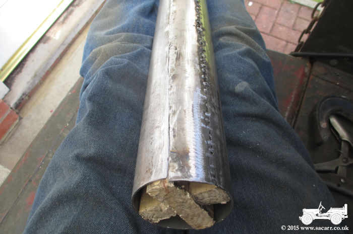
|
I cut a piece of the old tube to fill the gap and tack welded it down one seam. The other was overlapping the tube, and needed grinding and slitting with a saw to gradually reduce the diameter. It was while I was doing this that my finger slipped along a razor sharp edge, and I excavated a nice groove of skin from my knuckle and started pouring the red stuff everywhere. I packed up for the day soon after that!
|
|
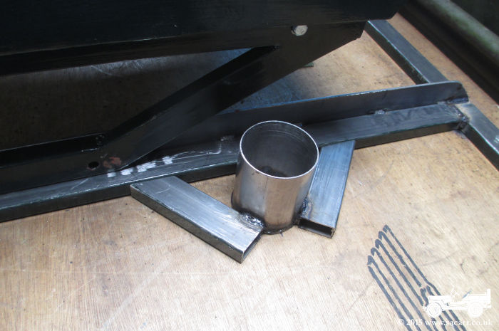
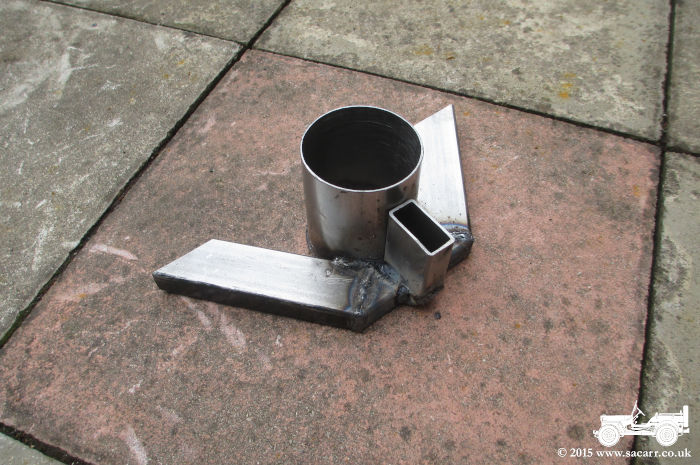
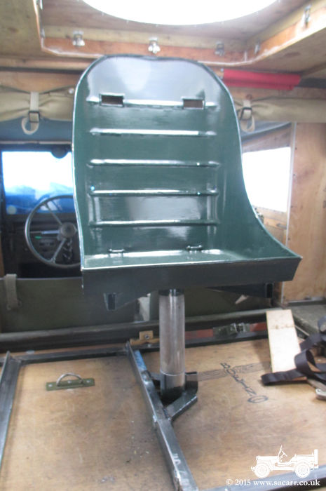
July 31st With little legs off to the lakes with the grandparents, I had another day free of childminding to work on the seat. This is the start of the support for the observers seat position, being offered up to the main frame to check alignment.
Most of this part was built in the workshop, and it wasn't until it was at this stage that it was moved to the truck and welded in. |
|
|
|
|
|
At first, I couldn't get the seat on! There wasn't enough height clearance to lift the seat over the post due to the backrest catching the roof. I trimmed an inch of the post and half an inch off the socket on the seat base, and that gave just enough room. To compensate for the loss of height in the seat post, I'll have to make sure Lynne makes the Army Air Corps seat cushion a little more padded.
|
|
|
The last metal work to go in. These diagonal braces help to steady the seat post, but also reinforce the bottom frame against the seat trying to lever forwards in an impact.
|
To finish the day, all the metal work was giving two coats of the dull dark green. This will now have to fully harden before the seat can be re-assembled for pictures of it all complete.
|
|
So bar putting it all back together and Lynne sewing the seat cushion, it's all done ready for Croft Nostalgia. That gives me a couple of days to check over the Dodge and Jeep before the trip South. |
|