| May 5th - Spring servicing and BC-375 Transmitter Fitted | |
|
I brought the Dodge home for the bank holiday
weekend to do the Spring servicing before the season gets under way. The
various fluids were checked or changed, the battery level topped up and given a
good charge.
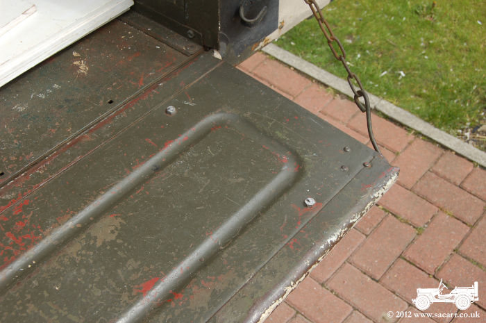
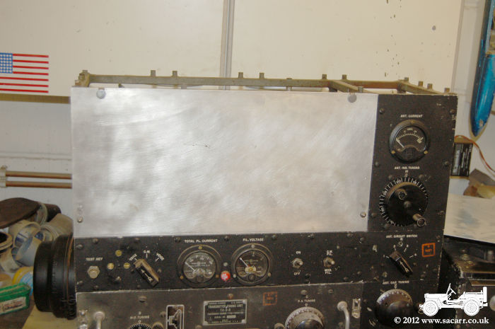
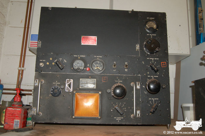
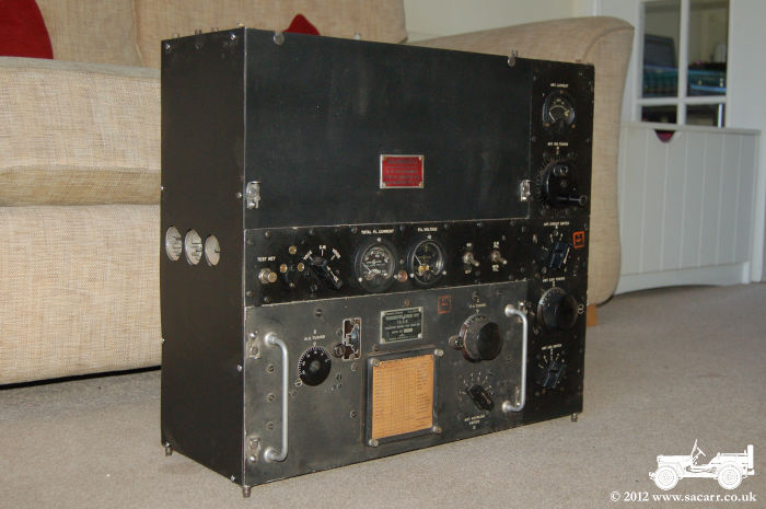
While home, it was the first chance to see if the BC-375 transmitter would fit on the shelf, since when I built the shelf, I was only working from transmitter dimensions I found on the net. Fortunately it fitted ok, so the mount was bolted in place. I'll keep the transmitter at home to continue work on the missing panels. Another small job done was to trim the pioneer rack bolts on the tailgate, as I'm in constant danger of ripping my HBT's climbing in and out. |
|
|
|
|
|
|
|
|
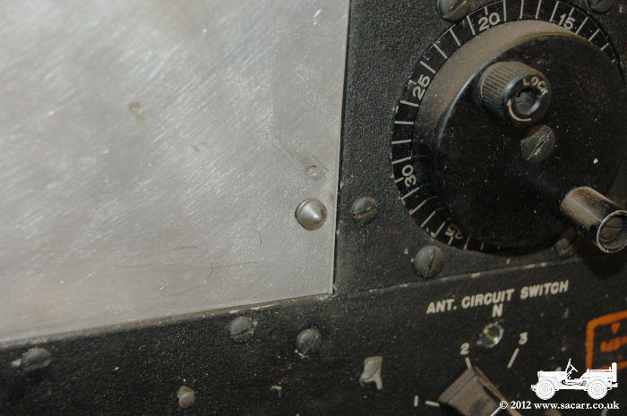
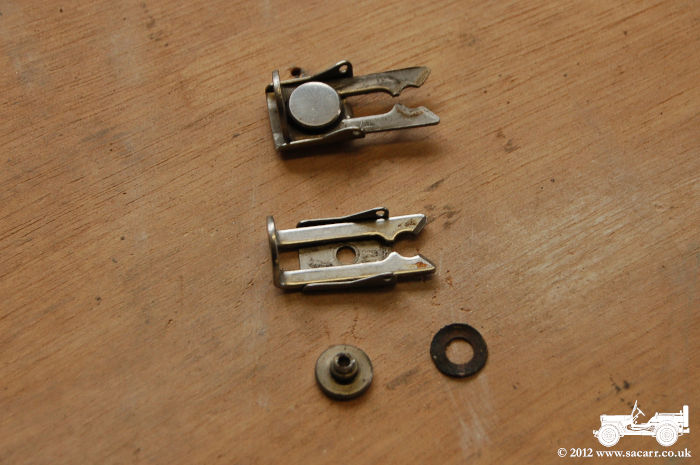
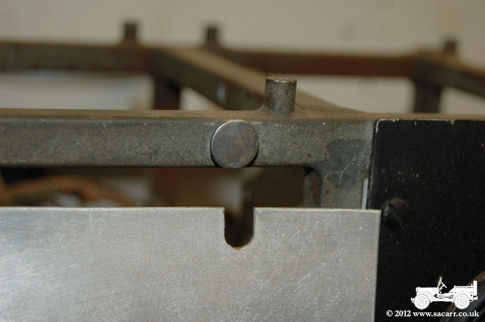
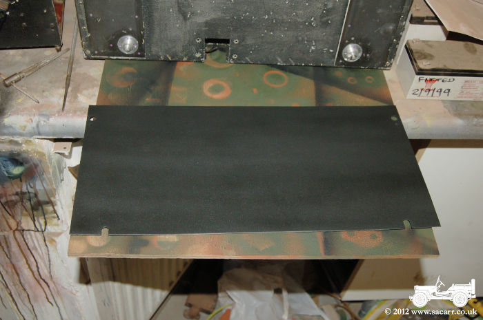
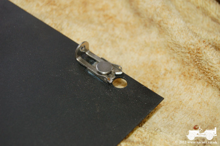
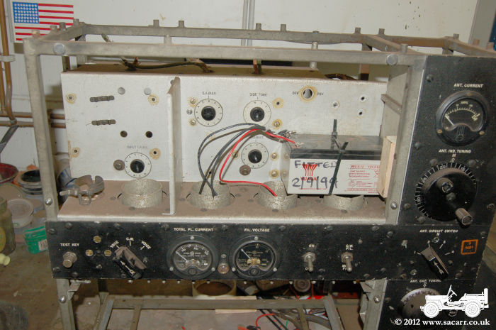
Until I can find original panels, or get louvred replacements made, I wanted the transmitter presentable in the truck. So for now, I've started making this plain cover to fill the opening where the valves fit. The aliminium sheet was notched at the top, same as the originals, to fit under the rivets, while the bottom was drilled to fit over the pins where the retaining catches fit. Fortunately I've got two of the catches which can be used. The catches are riveted in place, so I've carefully filed the rivet enough that the catch can be disassembled, the the cover plate drilled in the appropriate location for the rivets. The pin at the back of the rivet is a hollow tube, and I should be able to flare the tube out again to hold the catch onto the cover plate once the black paint is dry. Because of the position of the transmitter in the truck, the other missing panels aren't obvious. |
|
|
|
|
|
|
|
|
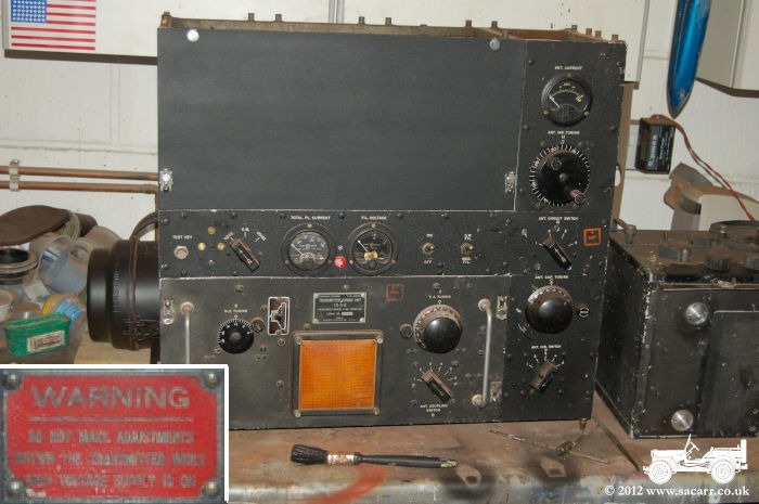
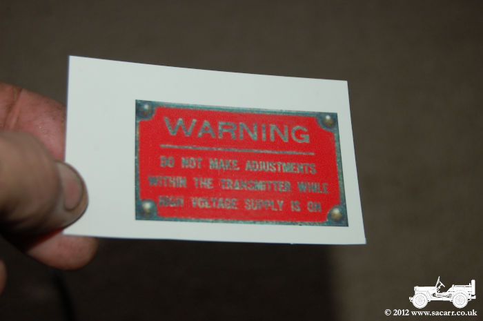
May 8th & 10th The panel was dry this morning so the clips were glued and riveted in place. The panel was fitted to the transmitter while the glue sets to make sure the clips are aligned correctly. Inset is the warning sign on the front of an original louvred panel. Below right is the printed warning sign on transparent waterslide paper. The red area needs cutting out and applying to a small rectangle of aluminium which can then be bolted to the panel. |
|
|
|
|
May 11th - Valve cover finished and fitted |
|
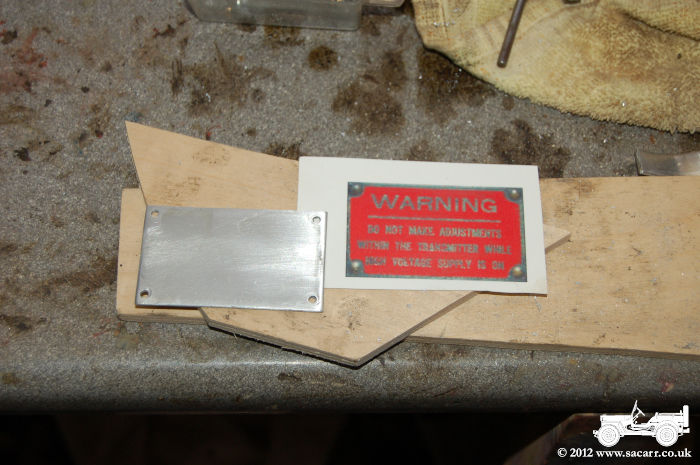
| The aluminium plate was cut and drilled, followed by a coat of clear gloss which would give the decal a smoother surface to adhere to. | The valve cover was removed now that the glue has fully cured on the retaining clips, allowing it to be drilled for the warning sign. |
|
|
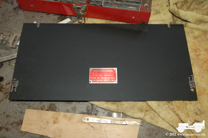
| The plate was positioned higher up the valve cover than it would be on the louvred panel to better balance the expanse of the plain panel. | Some small brass bolts hold the warning sign in place. It can be removed and fitted to the louvred panel once that is made, but for now, the transmitter is looking pretty good. |
|
|
|
|
|
|
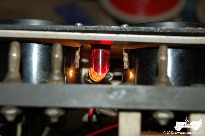
A new lens for the power light was turned on the lathe
today, and a
red acrylic reflector added behind the lens to direct the light from the bulb
through 90 degrees to the power light.
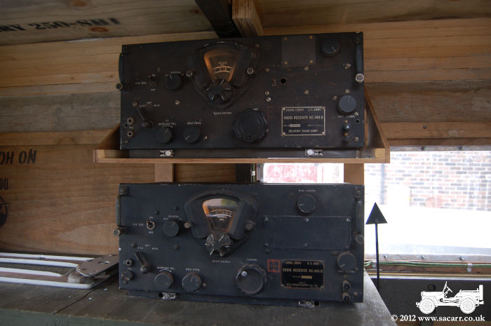
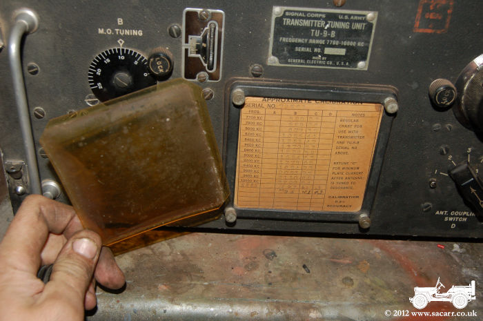
A small 12v battery was then installed in the valve compartment of the transmitter, which was connected up to the voltmeter, milliampre meter and power light. Now when the master power switch is thrown, the meters and power light come to life, giving the impression that the transmitter is working. A new clear cover was also made for the calibration chart as the original cover had badly yellowed with age.
|
|
|
|
| Later in the day, I got the end panel painted, and once it was dry, it was screwed to the end of the transmitter. | |
|
Here's an animation of the power light and
meters working.
|
|
|
|
|
|
|
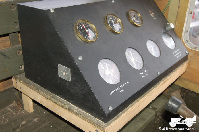
Something that has annoyed me for a while are
the two AA batteries that run the two clocks on the meteorological panel. The
cold sucks the life out of them, the clocks start running slow and then the
front of the panel needs unscrewing to replace the batteries and reset the
time. Today I replaced the two AA batteries with a single 2 volt rechargable
cell powering both clocks. A charging socket was then fitted in the side of the
panel to make topping up the battery a simple affair.
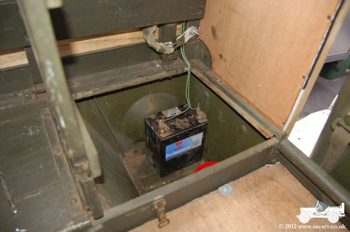
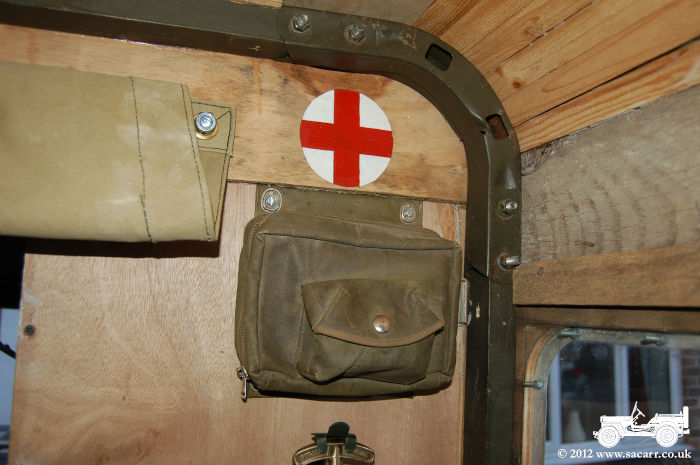
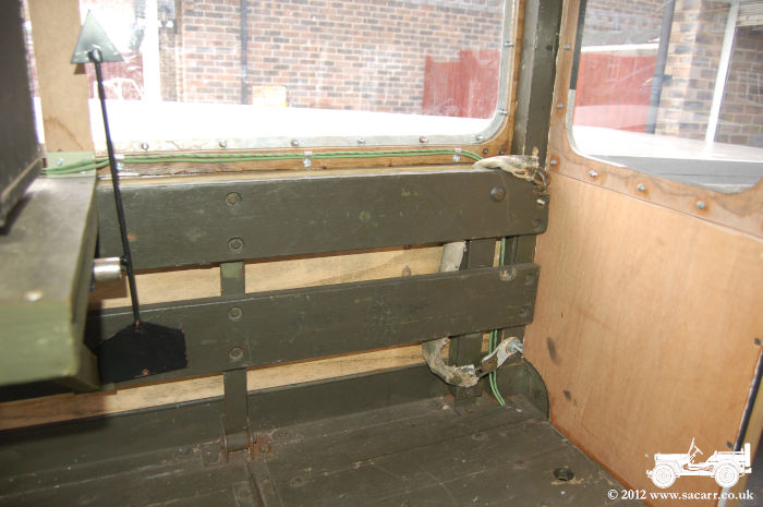
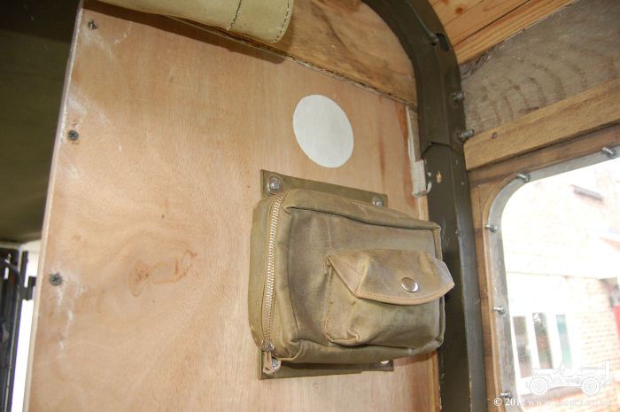
The next job was to add a 12 volt battery inside the front left locker. This will power the radios and also in time, the airband radio and amplifier. The wiring has all been done with cotton insulated cable which runs up the seat back and along the window edge to the radio trays. The final small job was to add the spare aircraft first aid kit to the front right panel in the rear body. The beginnings of a first aid symbol has been painted to clarify what the small wall mounted bag is. |
|
|
|
|
|
|
|
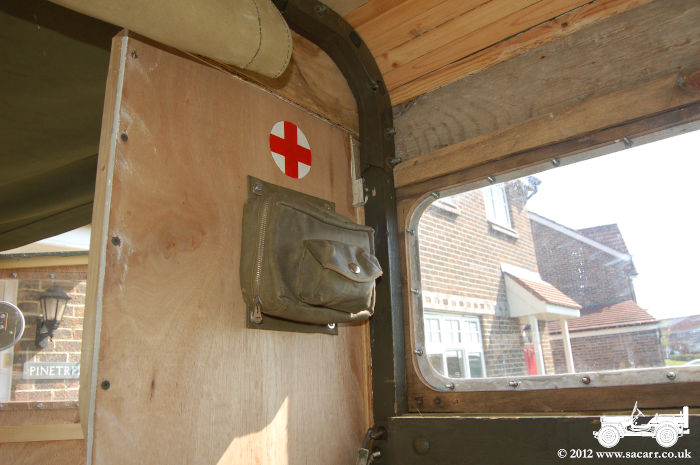
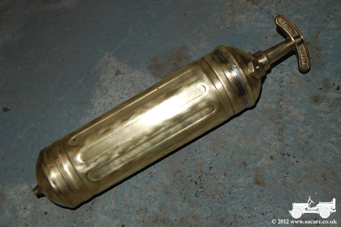
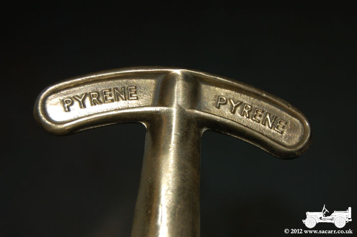
First thing this morning, I went out to the truck and painted the red of the red cross sign. There's still space below the red cross bag, and I have a spare Pyrene fire extinguisher, so that is to be fitted to that section of the truck. I've also ordered an airband radio this morning which I'm hoping will be here in time for the Elvington show this coming weekend. |
|
|
|
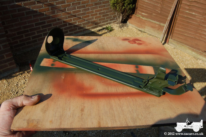
| The fire extinguisher was covered in paint and tarnish which was all removed with a rotary wire brush, back down to the original brass. It's a bit bright now, but clean, and will dull down in time. The steel mount was painted in a black enamel which had partially flaked away due to rusting. The mount was treated by electrolysis to remove the rust, and then given a coat of olive drab and left to dry. | |
|
|
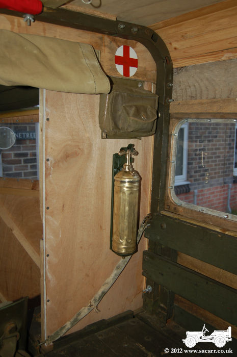
| The idea to fit the fire extinguisher came as an after thought following the fitting of the first aid kit. It had been lying around the workshop for a couple of weeks, and seeing the empty spot below the first aid kit, it seemed the ideal place to fit it. | |
|
Unfortunately, after thoughts don't always
work as unplanned! I suddenly had a worrying thought; would the locker open
past the extinguisher mount? Simple answer was no! As a result, the first aid
kit was moved up about five inches, the red cross was repainted above it, and
this left just enough room for the mount with clearance for the locker lid.
|
|
|
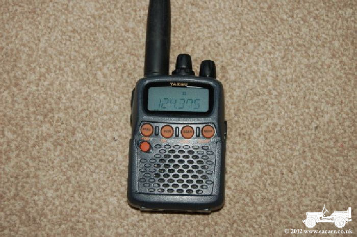
May 23rd - Installing the Airband Radio There's not much in the way of pictures to show for work done today, but I feel I've made a big step towards bringing the radio truck to life. It started about 8:15am, when the postman delivered the airband radio. I was just going to hide it in the corner of the truck for the Elvington show, but had time and better ideas. The 12v amplifier from the Jeep was removed. It's only connected by plugs and sockets, so it wasn't an issue to remove it. After searching around the house, I found a lead with a mono 3.5mm earphone jack to connect to the airband radio, and a phono plug on the other which would fit the amp. |
|
|
I contemplated lifting the speaker crate out
of the Jeep, but it is quite big, and wouldn't fit in the Dodge easily on the
side of the radios. Instead, I opened up the original Signal Corps LS-3 loud
speaker and made a test connection between it and the amplifier. It worked
which was good news, as I had visions of having to buy a new speaker to hide
inside the original LS-3 case.
I thought about wiring the speaker into the locker where the amp and battery would be, but it didn't look connected. Instead I made up a double ended jack lead from more of the cotton bound cable I had. One end plugs into the front of the speaker, while the other end plugs into the BC-366 Jack Box under the radio shelf. Two wires from in the jack box are then routed out of the back under the radio bench and along the window with the radio power cables installed the other day. They then drop into the front locker and connect to the amp. |
|
|
Now with everything connected and powered up, all the radios light up and the airband radio broadcasts its audio through the original speaker which sits under the radio bench. All being well, those coming to the 'Battlegroup North' show at the Yorkshire Air Museum this weekend can see and hear it in action. |
|