| November 15th - Radio Installation Planning and Equipment Mounting Clips. | |
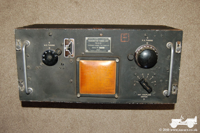
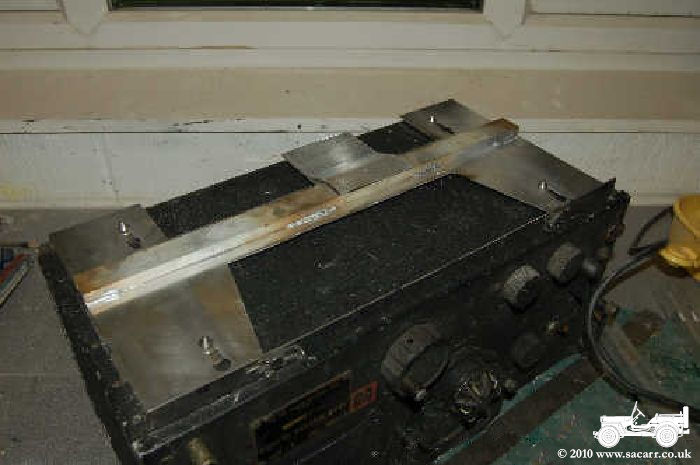
| Another
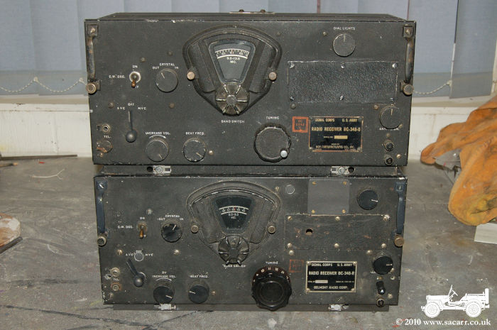
recent purchase is this BC-191 Tuning unit, part of a BC-375
transmitter. Complete transmitters, if they become available are asking
serious money, so I decided to buy the tuning unit and build the rest
myself.
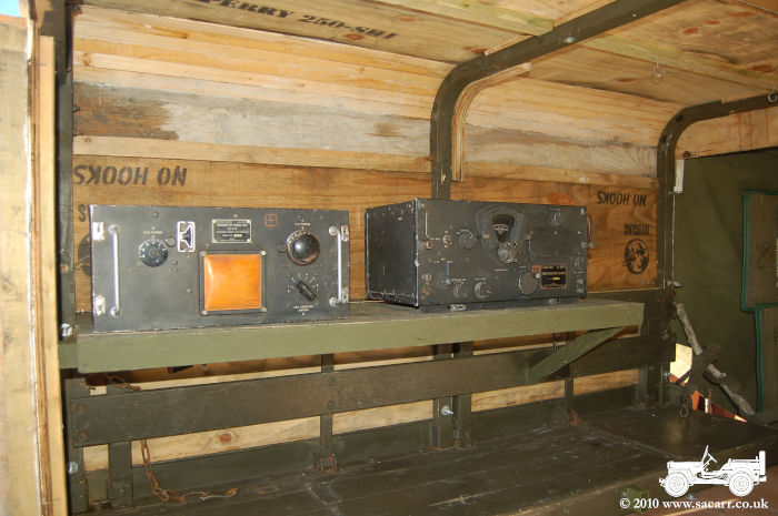
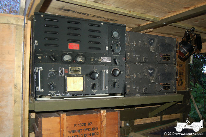
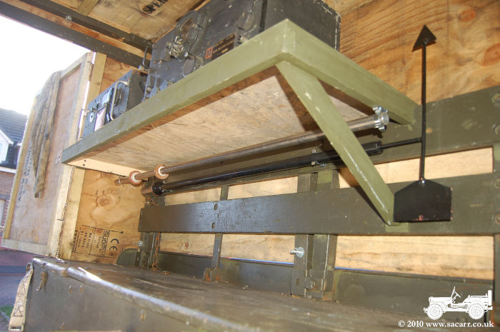
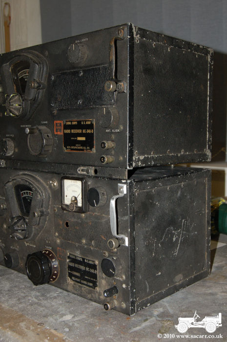
The tuner has most of the complicated parts, and I should be able to take moulds of the knobs to cast more for the rest of the unit. The only other difficult parts to make will be the gauges and louvres. The picture below shows the BC-191 along with the BC-348 on the radio shelf, working out positioning and spacings, while the picture to the lower right shows a composite picture with a BC-375 image overlaid. The final set up should be something similar to this, although I will need to add a second shelf to support the other BC-348 receiver. |
|
|
|
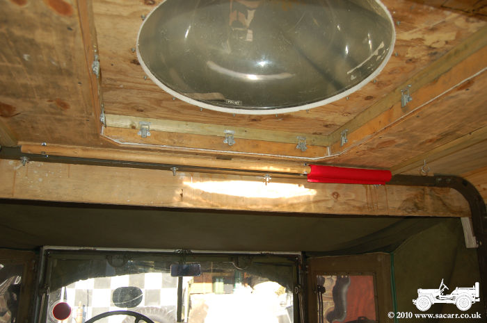
| Before the weekend trip out, I also fitted six mounting clips to fasten in the warning flag, the weather vane and part of the child seat mount when not being used. I also fitted a switch into the meteorological panel for the panel light and partially wired up the light with the recently purchased cotton insulated wire. | |
|
|
|
November 7th - Fitting Retaining Clips. |
|
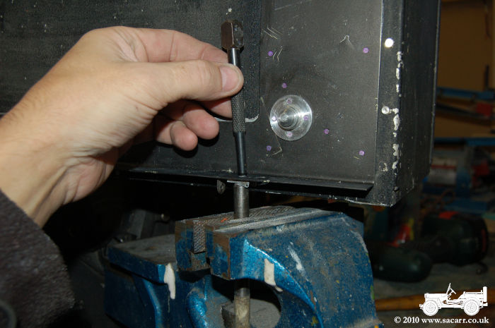
| Once the
base was dry, the retaining clips could be fitted. The spigot on the
back of the rivet I made was drilled out with a 1.5mm drill to allow it
to splay out. A little Hysol was put on the backplate of the clip and
the assembly put in place.
The case was then balanced on its front, with the rivet head resting on a large drill bit clamped in a vice. I then used a centre punch to splay out the back of the rivet. The two radios are now ready for their FT-154 mounting trays to be made. |
|
|
|
| FT-154 Radio Mount. |
|
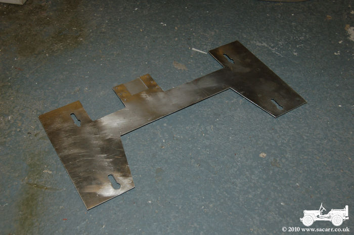
| The
FT-154 Radio Mount is made in two layers. The lower part fastens down to
the radio operators table. There are four rubber mounts attached to
this, and on top, a metal tray that the radio attaches to.
I started my copy by making the upper part of the mount. The 1.5mm aluminium was cut to the correct shape, and then the ends of the slots drilled with a slightly under size drill. They were then filed to elongate the slots to the correct length and width. After much filing, the tray was trial fitted onto the receiver to ensure it was sliding freely. |
|
|
|
|
|
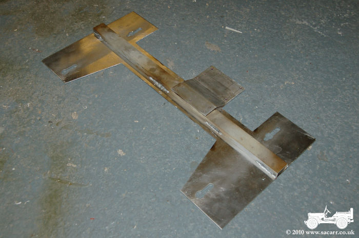
| On the bottom of the tray, there is a 'U' channel. This stiffens the sheet and also forms part of the brace for the electrical socket mount. This brace was made from an off cut of the 1.5mm sheet, folded to drop the height from the top of the channel to the main plate. This brace was riveted to the channel, which was in turn was welded to the sheet at four spots along its length. The socket mount was then riveted to the tray. It still needs the hole cutting to fit the socket. | |
|
|
| This
is where the day ran out and the mount was refitted to make sure the
welding hadn't distorted the fit. It was then removed again, placed on a
flat bench and a small fillet of Hysol applied along the edge of the
channel.
The next stage will be to make the second upper tray before moving onto the shock mounts and the lower parts of the trays. |
|
|
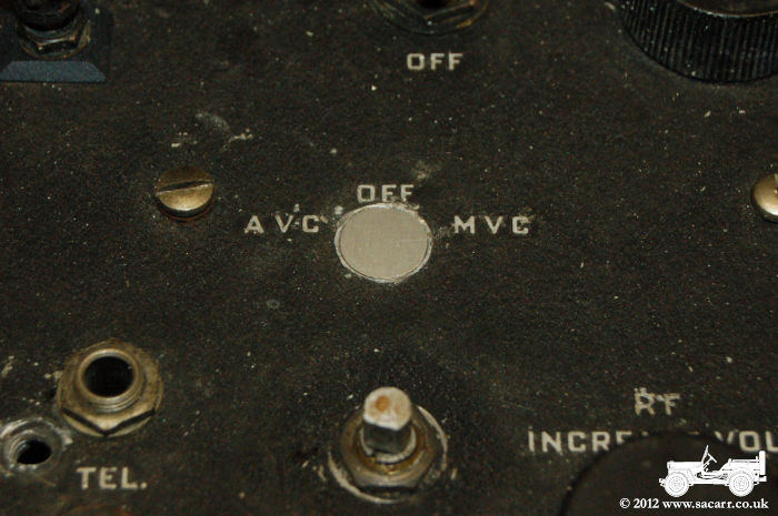
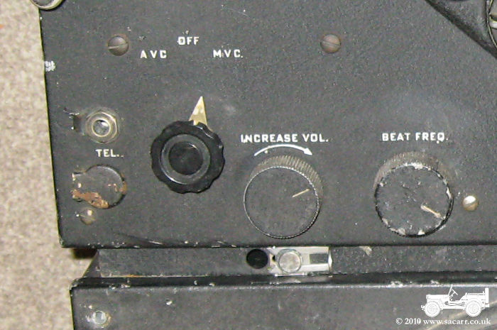
November 6th - BC-348 Replacement Panels and Switches. On the new receiver, there were several features that were none wartime, such as the meter and a couple of switches. I have seen a video on Youtube about modifications to improve the receiver that match the changes made to this radio. The switches were removed and small aluminium discs cut and filed to fit the holes. The meter left a large hole, so this was just covered over with a thin aluminium panel. After trial fitting, the two discs and the square panel were all etch primed, followed by a hammered finish black. |
|
|
|
|
 |
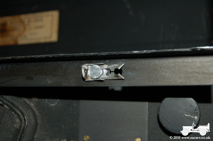
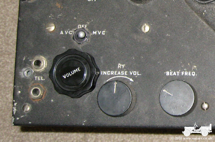
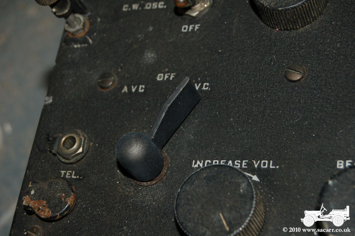
| Both the
new receiver and the original one had the incorrect switch on the
AVC/MVC control. On the new receiver, there was a rotary control and an
additional switch had been fitted. The switch was removed and the hole
filled as shown above, and both of the rotary switches removed.
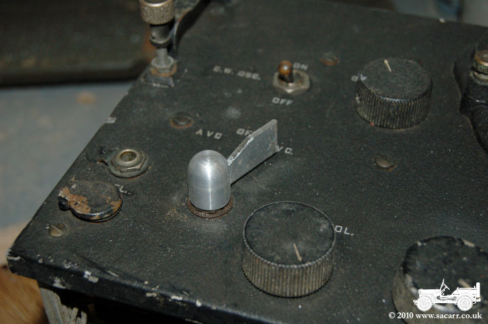
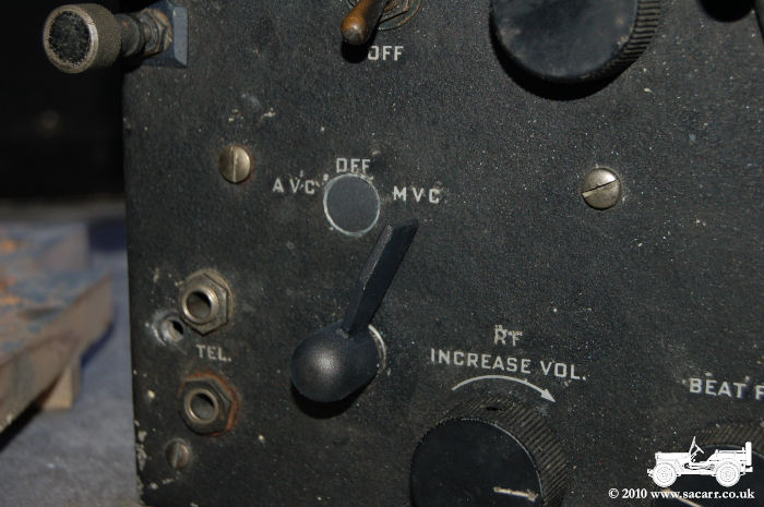
Two new switches were machined from aluminium. The main bodies were turned on my lathe, while the arm cut and filed from flat sheet which was then welded on. The main body was then drilled and tapped for an M3 screw and a bolt cut down and slotted to form the set screw that holds the assembly in place. |
 |
|
 |
|
 |
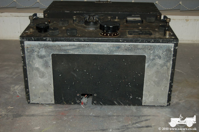
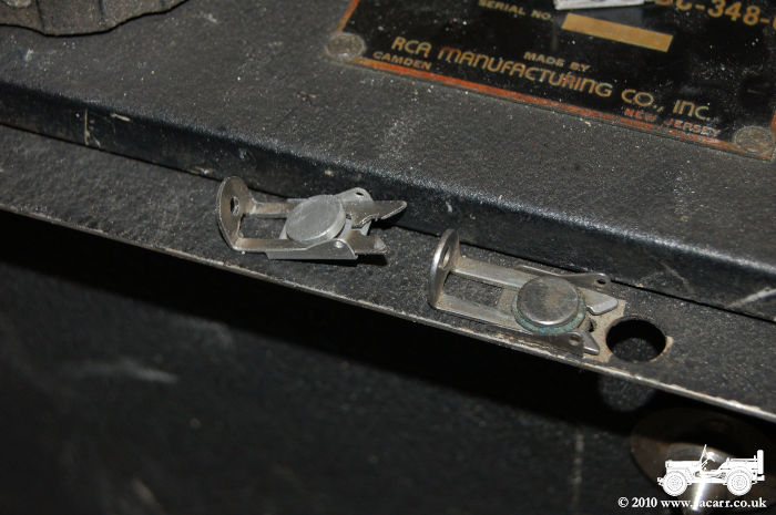
| BC-348 Mounting Plate. |
|
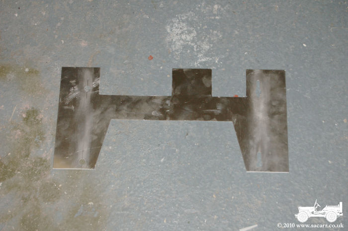
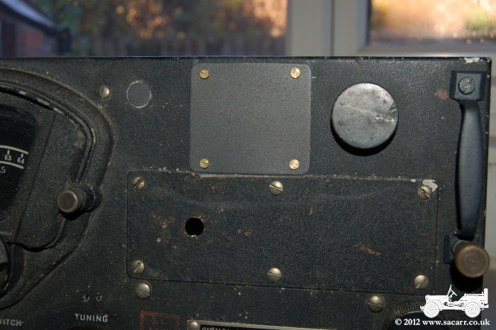
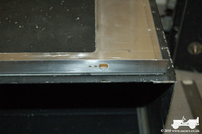
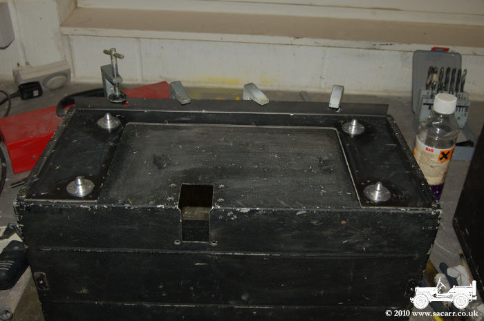
| As can be seen in the picture below left, the mounting plate is missing. This plate connects the receiver housing to the FT-154 mounting tray. So, after a quick visit to the farm to give the truck a run, I bought some aluminium sheet and bar to replace the missing mounting plate, and to make two FT-154 receiver mounts. | |
|
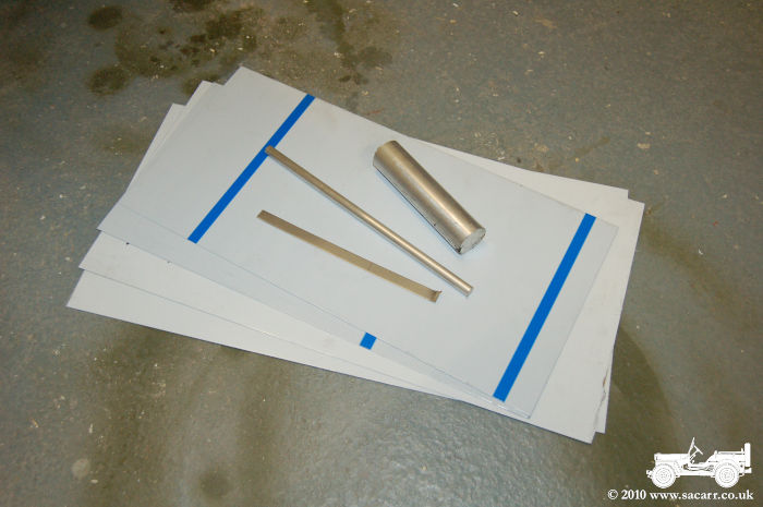 |
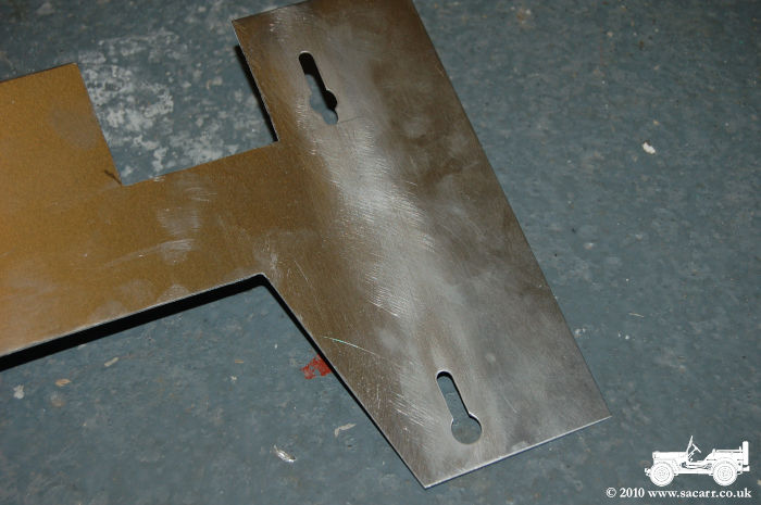
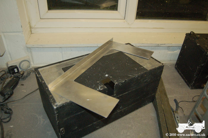
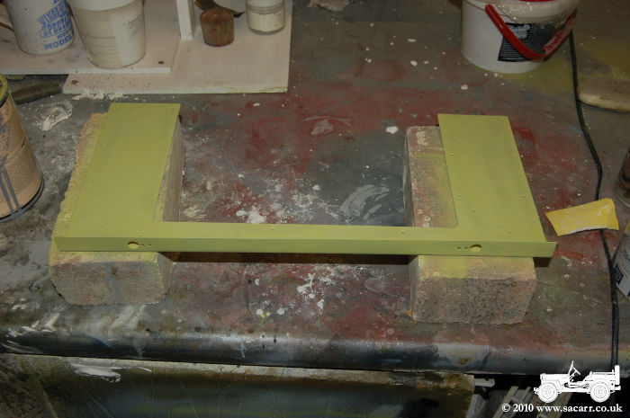
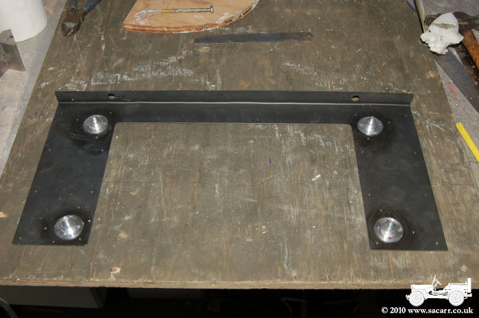
| I annealed the aluminium sheet along the fold line first, then clamping the sheet between two pieces of wood, folded the front lip. The rectangle was cut out next with a metal nibbler, then dressed with tin snips and a file. The holes were drilled next for the mounting pin and retaining clip. | |
|
 |
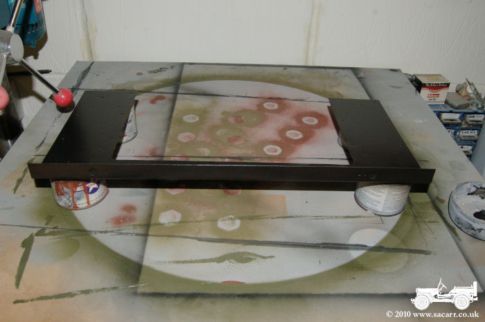
| The tray was then drilled to match the rivet holes in the radio housing, etch primed, and when dry, sprayed with the hammer finish black. That is hardening overnight, and will be given a matt clear coat before fitting. | |
|
 |
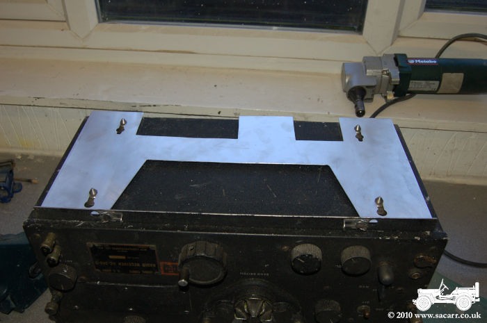
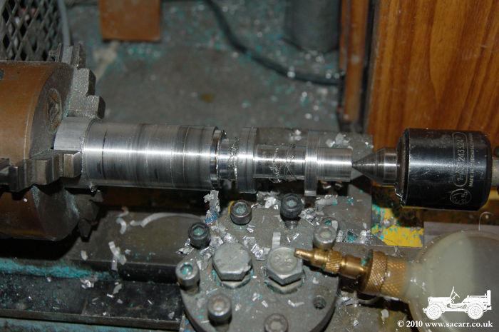
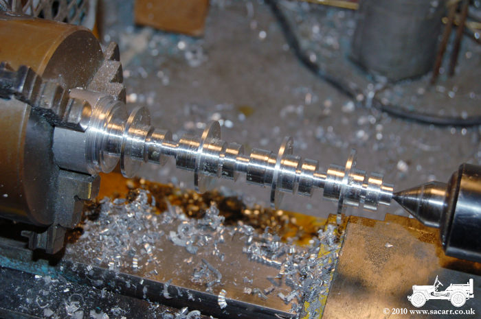
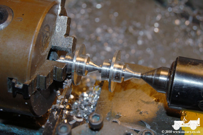
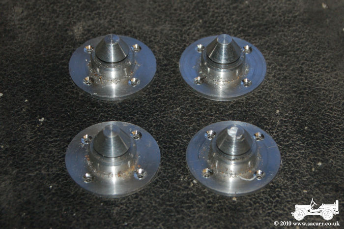
| The next job was turning the four metal spigots that locate into the mounting tray. All four were turned on one 30mm aluminium bar. Once the taper was machined, they were parted one by one, and then the four mounting holes drilled. | |
|
 |
|
 |
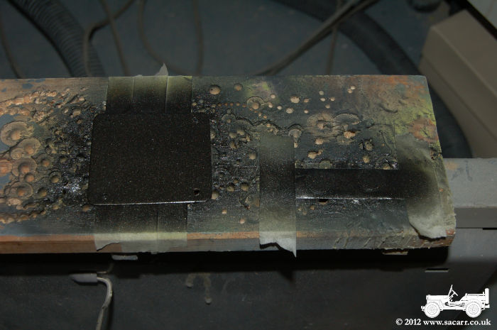
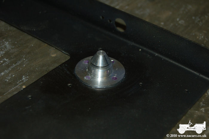
| The paint was cleaned away under where the mounting spigots were to go. In addition to the four rivets, I took the precaution of using some 24 hour Loctite Hysol 9462 epoxy. | |
|
 |
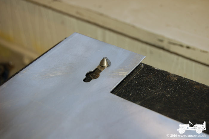
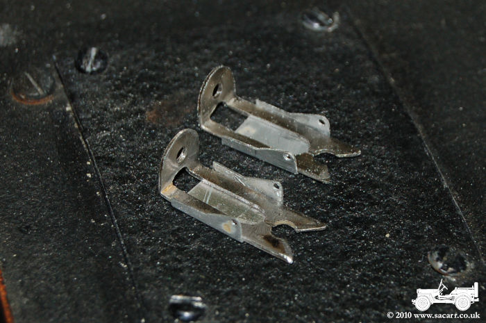
| The mounting plate was also riveted onto the radio case, and this was also glued for additional security. While that was curing, I made a start on the retaining clips. I had wanted some bright steel strip, but couldn't get any thin enough, so ended up with stainless steel. This was very hard to work, but after drilling the holes, the slot was cut with a miniature stone cutting disc. | |
|
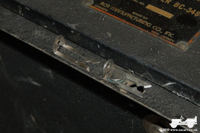 |
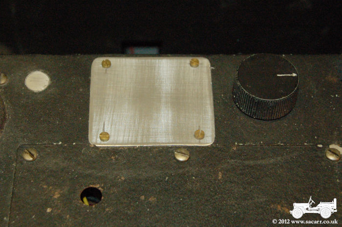
| The base plate for the retaining clips were made from 0.25mm aluminium sheet, and then a turned rivet was made which will hold the clip onto the mounting plate. The new clip is shown below next to the original on the first receiver. | |
|
 |
|
November 1st - Handles for BC-348 Receiver. |
|
| Today I
spent a few hours making replacement handles for the new BC-348 radio.
Originally I was going to cast them, but the plaster I use for mould
making had gone off and wasn't setting properly.
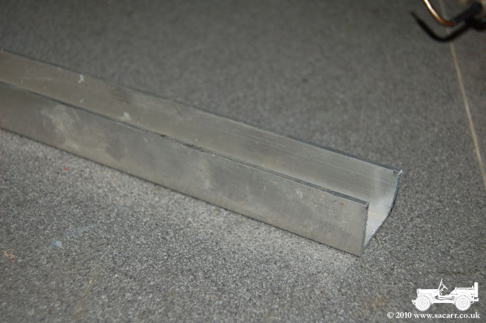
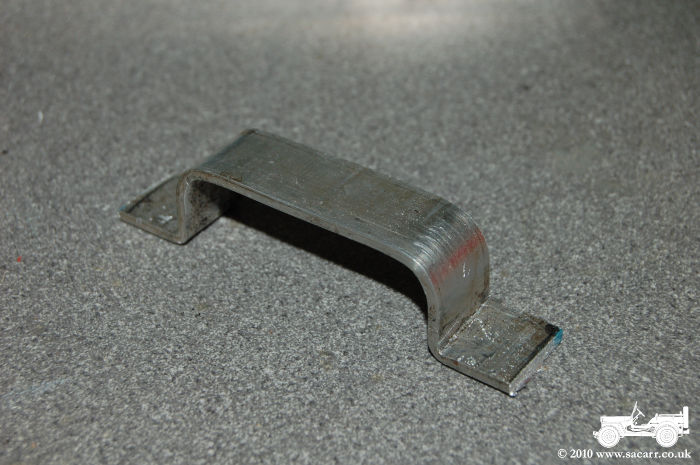
Instead I decided to make them from flat sheet. I didn't have any sheet aluminium, so had to cut some strips from some channel section. This was then annealed, and the main arched folded around a shaped block. It was re-annealed and the end lugs folded over. The holes were drilled next, then final shaping done with various files, followed by a light rub over with wet and dry paper. |
 |
 |
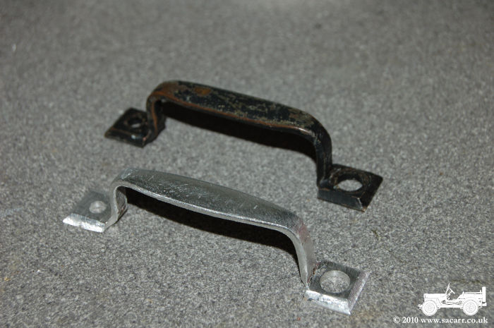 |
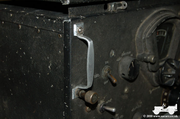
| Close up
of one of the new handles fitted to the radio prior to painting.
|
 |
|
|
Both
receivers now fitted with the new 12 volt bulbs, and the new handles
painted .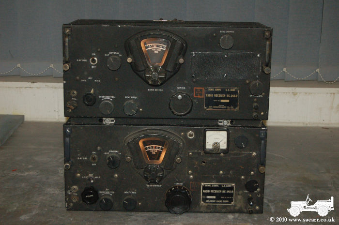 |